I2C PCF8574 all leds on outputs flicker as each one is turned via 20X2

pmulvey

New Member
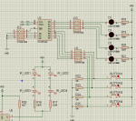
The code below is cycling a bulb from dark to bright and back again using h12cout to a L293D motor driver chip on my 20X2 board. This works great and was just a test. I also sent a binary count sequence to four leds on the PCF8574 chip and notice that as they change state a visible flicker occurs on all OFF LEDS. SDA and SCL are tied to VDD via 4k7 resistors.
Any ideas??
Code:
Symbol IN1 = b.1
Symbol IN2 = b.2
Symbol IN3 = b.3
Symbol IN4 = b.6
Symbol i = b51
Symbol j = b50

HI2CSETUP I2CMASTER, $40, i2cfast, i2cbyte	

Start:	
sound Speaker, (110,10)


gosub BulbTest1
goto Start

BulbTest1:
	j = j + 1
	j = j & 15
	j = NOT j 
	i = 20

		
	hi2cout 0,(j)
	for w = 30 to 1020 step 70
		Speed = w
		gosub SetSpeed
		gosub MotorA_FWD
		pause i
	next w

	
	for w = 1020 to 30 step -70
		Speed = w
		gosub SetSpeed
		gosub MotorA_FWD
		pause i
	next w

	hi2cout 0,(j)
	j = NOT j			;reinvert j for counting purposes
return

MotorA_FWD:
	high IN1
	low IN2
return

SetSpeed:
	hpwm PWMDIV16, 0,0,%1000,255, Speed
return
 
Last edited by a moderator:

pmulvey

New Member
Corrected code...

Pulled original code from a bigger program, this should be OK:
Code:
Symbol IN1 = b.1
Symbol IN2 = b.2
Symbol IN3 = b.3
Symbol IN4 = b.6
Symbol i = b51
Symbol j = b50
Symbol Speaker = c.7
Symbol w = w26
Symbol Speed = w27

HI2CSETUP I2CMASTER, $40, i2cfast, i2cbyte

Start:
sound Speaker, (110,10)


gosub BulbTest1
goto Start

BulbTest1:
j = j + 1
j = j & 15
j = NOT j
i = 20


hi2cout 0,(j)
for w = 30 to 1020 step 70
Speed = w
gosub SetSpeed
gosub MotorA_FWD
pause i
next w


for w = 1020 to 30 step -70
Speed = w
gosub SetSpeed
gosub MotorA_FWD
pause i
next w

hi2cout 0,(j)
j = NOT j ;reinvert j for counting purposes
return

MotorA_FWD:
high IN1
low IN2
return

SetSpeed:
hpwm PWMDIV16, 0,0,%1000,255, Speed
return
 
Last edited by a moderator:

pmulvey

New Member
Some more investigation...

Referring to the attached scope screenshot...
I monitored the SDA line (Yellow trace) and monitored P1 (Blue Trace). The program toggles P0 as it should but P1 toggles in the middle of the SDA data burst as well.
Don't know what is happening.
 

Attachments

pmulvey

New Member
Code and schematic

This is the code:

HI2CSETUP I2CMASTER, $40, i2cslow, i2cbyte
I2CTest:
hi2cout [$40],0,(%00001110)
pause 2
hi2cout [$40],0,(%00001111)
pause 2

goto I2CTest


I also tried this but same result:
hi2cout 0,(%00001110)
 

Attachments

hippy

Ex-Staff (retired)
hi2cout [$40],0,(%00001110)

That will send three sets of data to the PCF8754; device address $40, $00 then $0E. The $00 and $0E will be taken as data to output therefore P1 will be set low then fairly quickly set high.

In fact, that is likely exactly what you are seeing in the scope trace attachment; the zeroing is before the Ack for $00 until to the Ack for $0E.
 

pmulvey

New Member
If I had the good sense to Read The Fine Manual more carefully I might have seen that I was sending out two data bytes along with the device address. I take it that the location address for the PCF8574 port is by default $00 and is not specified. I probably copied the hi2cout command from another program that was doing operations on a RTC chip where there are multiple locations at the device address. Am I right hippy?

Thanks for your help
Paul
 

hippy

Ex-Staff (retired)
I would agree it's probably a copy and paste error, using code for a device which needs a register / memory location address when the PCF8574 doesn't ( only has one location so that's implied ).

A simple "HI2COUT ( %....... )" should do the job.
 

westaust55

Moderator
A simple "HI2COUT ( %....... )" should do the job.
It certainly will. Here are a couple of subroutine I wrote long ago to control LEDs driven by PCF8574 chips.
Keep in mind my 40X1 code was working with many i2c devices on the i2c comms bus together so needed to establish the setup/slave address for each device prior to read or write operations.

Code:
; PCF8574 8-BIT IO EXPANDERS
SYMBOL expand_0 = %01000000  ; %0100 = Chip ID, 000 = Addr 0 - For 8 LED's as a bargraph
SYMBOL expand_1 = %01000010  ;                , 001 = Addr 1 - For Keypad Shift LED

; -----[ Subroutines ]-----------------------------------------------------
;
Pattn2led: ; Subroutine to output 8-bit pattern to row of LEDs       
           HI2CSETUP i2cmaster, expand_0, i2cslow, i2cbyte 
           HI2COUT (pattern)
           RETURN
;
;
Shlok2led: ; Subroutine to togggle the keypad "SHIFT" LED
           HI2CSETUP i2cmaster, expand_1, i2cslow, i2cbyte
           IF shflock = 0 THEN
             HI2COUT (0)
           ELSE
             HI2COUT (1)
           ENDIF
           RETURN
 
Top