i2c bus speed - any restrictions?

westaust55

Moderator
Like the good Dr, Acula, I have seen references on this forum suggesting that if there is one slow (100kHz) component on the i2c bus then the the bus is forced to always run at the slow speed.

Well thinking about what I and others (may) have on their i2c buses and the speeds of these devices:

1. DS1307 RTC = slow (I have a separate RTC as well as in the AXE033)
2. AXE033 LCD = slow
3. PCF8574 IO Expander = slow ( couple in my case )
4. 24LC256 EEPROM = fast (several added in my case)

a few things others have mentioned:

5. MCP23016/7 IO Expander = fast
6. MCP23008 IO Expander . . = fast
7. SRF08 U/S Range finder . = fast
8. CMPS03 Compass module = fast
9. SP03 Speech Syn Module = fast

Also noted of general interest from BCJKiwi code snipped that:
if the CMPS03 is wired to the i2c bus but not powered up (i.e. v+ disconnected), it 'kills' the i2c bus. So if you are working with a CMPS03, ensure it is fully connected and powered up, or, disconnect it from the bus at the preceding device - i.e. no floating wires. Other devices (e.g. DS1307) did not exhibit this behaviour.
So in conclusion,
1. many people have a slow devices in the form of an DS1307 RTC or an AXE033 and a few out ther also some have PCF8574 IO Expanders.
2. most other devices appear to be fast (400kHz) bus speed.

I for one currently have items type 1, 3 and 4 so a mix of slow and fast devices and no problems experienced to date.

Maybe some erudite peron can point at a specific i2c spec or datasheet that indicates problems WILL be experienced. :confused:
 
Last edited:

hippy

Ex-Staff (retired)
There is unlikely to be anything which says I2C "will fail" if a slow speed device encounters high-speed I2C on a bus but it can be shown that there are circumstances which can cause it to interfere with the bus which can lead to failure.

The real world analogy ...

You're a slow device looking out your home's front window, next door your neighbour is a fast device looking out their window, and in the street is the master device with some semaphore flags.

As a fast device your neighbour will see every flag indication given by the master, get the message and do what's asked.

You on the other hand as a slow device only look once every ten seconds say. You will still see a sequence of flags and read a message. Often it will be incomplete, garbled or make no sense but sometimes it may make sense and you will do what it says even if that conflicts with what instruction was being given to the fast device.

There's your neighbour trying to tell the master the temperature as asked while you've completely misunderstood what was being asked, have put a gag on on your neighbour, and are shouting back "It's Tuesday'.
 

hippy

Ex-Staff (retired)
Another more technical problem comes where the master is using hard-driven I/O lines to control the bus rather than using a floating / open-collector interface. If the master is outputting a high and a slave pulls the bus low ( because that's what it thinks it should be doing ) you have a dead short of that I/O pin to 0V. A 'small puff of smoke' and you have no I2C, perhaps no PICAXE.
 

westaust55

Moderator
Thanks Hippy.

Fully understand your explanation.

I guess it is a case of me waiting to see if I have any problems and then at leasting knowing I can try with all devices at the slow speed to see if problem goes away. I guess any such problem may likely be intermittant as well - that is only occur once in a while as opposed to continuously.
 

Technical

Technical Support
Staff member
If the master is outputting a high and a slave pulls the bus low
That should never happen - by default a master implemented on something like a PIC should use 'output low' to pull the bus low and 'input - high impedance' to allow the resistor to pull the bus high. Therefore there should never be an 'output high' situation.

Building a master that works with an output high is asking for trouble!
 

hippy

Ex-Staff (retired)
True, it shouldn't happen but it is a problem with some bit-banged software drivers or where outputs cannot be made inputs - usually solved by a diode, pointy-end to I/O pin which effectively makes that open-collector.

It also applies to the SCL line if a slave device tries to force clock-stretching or multi-master mode is used. I can name a 'well known and very credible company' with a commercial demo product that doesn't have pull-up on SCL and thus needs to be hard-driven, and as that's done by on-chip ROM firmware to facilitate booting, it still hard-drives during booting even on their boards where there is a pull-up !

As you say, "just asking for trouble".
 

BCJKiwi

Senior Member
@Westaust55
If you follow through the full thread
http://www.picaxeforum.co.uk/showthread.php?t=8535
(from which you have taken the above quote), you will find additional relevant info - Technical post#5;
"It does appear that the i2cslow and i2cfast constants are incorrect (the same) in the current 28X1 compiler - we will fix in the next compiler release. However as these are simply predefined constants you type in your own number instead to set your own speeds for the PICs i2c baud speed generator."
This applies to the 28X1 rev a.1 but fixed later. This explains why some have no problems with mixed bus speeds - the bus is really running slow (100K) even when set to high (400k).

Also from Technical post #9 in the same thread,
"You cannot run mixed speed devices on the same bus and use the higher baud rate - the slow device will simply get confused and can hang or give corrupt data. The max baudrate you can use is the max baudrate of the slowest device on the bus - as you have proved by experimentation!"
 
Last edited:

Brietech

Senior Member
does anyone know what the max baudrate is for a 28x1 running in slave mode? i.e. can it keep up with 1 Mhz devices? (I have several 1 Mhz memory devices on the same bus as a 28x1 slave)
 

BCJKiwi

Senior Member
As per this table from the thread referenced above, if you crank up the clock speed and reduce the 'mode' number you should be able to get to 1Mhz.

The pullups will also need to be tweaked to ensure you get a fast enough rise time on the bus to ensure proper switching - scope required!

Higher speeds will also mean shorter bus length.

Bear in mind there is no magic about the actual speed provided it is not too high. The bus is specified as 'up to xxxMHz' and the i2c bus is level triggered, not time triggered. A 1MHz bus can run at 100, 400, 715 or whatever provided it is not above 1MHz.

There is a wealth of info on i2c here;
http://www.i2cchip.com/index.html

Code:
Functional Mode Parameters
    hi2csetup       PICAXE      i2c
    MODE            Clock       Clock
    ----------------------------------
    i2cany          any         32KHz
    137             4MHz        100kHz
    147             8MHz        100kHz
    167             16MHz       100kHz
    1               4MHz        400kHz
    4               8MHz        400kHz
    9               16MHz       400kHz
    For example:- 
        hi2csetup i2cmaster,RTC_0,167,i2cbyte
        where RTC_0 is the device address
    Speeds verified with an oscilloscope
    for a 28X1 at 16MHz clock speed.
 
Last edited:

westaust55

Moderator
i2c bus speed

Thanks BCJKiwi,

"It does appear that the i2cslow and i2cfast constants are incorrect (the same) in the current 28X1 compiler - we will fix in the next compiler release. However as these are simply predefined constants you type in your own number instead to set your own speeds for the PICs i2c baud speed generator."
This applies to the 28X1 rev a.1 but fixed later. This explains why some have no problems with mixed bus speeds - the bus is really running slow (100K) even when set to high (400k).
Yes I read that but as I have a very new 40X1 have not seen reference to the same fault. Maybe I need to check the value constants tonight for mine.

Is the i2c bus speed the reason you are trying to buy a DS1337+ real time clock. I see they are 400kHz bus compatible (and have 2 time alarms but no battery backup connection at pin 3 or internal user RAM)


For Brietech,
in theory, you can operate the i2c bus at 1MHz but not at PICAXE standard 4MHz speed. You will need to change the frequency to 8MHz (then use BRG value of 1) or 16MHz (and then use BRG value of 3).

I have seen reference/suggestion to using 4.7 kOhm pull up resistors for 100kHz and 1.8 kOhm resistors for the 400kHz i2c bus speed. That may give some indication on what direction to start in for a 1MHz i2c bus speed.
EDIT: found a reference on the Deventech website to using 1.2 kOhm resistors for 1MHz i2c bus speed.
 
Last edited:

westaust55

Moderator
PCA8574 = 400kHz i2c bus speed

Now there is a new version (well its only been out for a year) of the PCF8574 from Philips, the PCA8574 and PCA8574A
these are 400kHz bus speed compatible.

The IC can handle a total of 200mA so it is possible to sink 25mA on ALL 8 outputs simultaneously.


EDIT: Hmmm will have to re-check to labelling on the top of my i2c 8-bit expanders tonight.
See whether I got PCF or PCA type. I did in error run them for a while with i2cfast setting and had no problems.
 

Attachments

Last edited:

hippy

Ex-Staff (retired)
does anyone know what the max baudrate is for a 28x1 running in slave mode? i.e. can it keep up with 1 Mhz devices? (I have several 1 Mhz memory devices on the same bus as a 28x1 slave)
Yes / No / Possibly ... Assuming the hardware can keep up ( may require 8MHz/16MHz osc ) you'll be okay talking to other devices. When it comes to sending data to the 28X1 I don't know what happens then. There will be some time while the firmware reads the byte and stores it in the scratchpad and updates flags and pointers. The 28X1 may do clock-stretching so it doesn't matter what speed it's run at, or ... you're going to have to start studying the 16F688 datasheet !
 

BCJKiwi

Senior Member
@Weastaust55
Yes that is exactly why I'm trying to source a DS1337+ - The DS1307 is the only device in the current project that is <400MHz. Have not yet found a commercial source and after (I think now 4) orders/re-orders of samples from MAXIM since November still no delivery!

If anyone has a source for NZ that does not cost the earth I would like to know. There also appears to be an issue with the DS1337+ in that it should use a 6pF crystal instead of the normal 12pF crystal else the timekeeping is off. Have not been able to find a source for those either.

The hi2cSetup speed issue was actually a programming Editor issue, not a chip version issue.
 

Ralpht

New Member
Looking at Westaust55's original post and question -

there is no reason for problems to occur. If there are a mix of fast and slow I2C devices on the bus, the bus will run at the speed of the slowest device. That will not cause any issues since all the fast chips will be backwards compatible and run slow quite OK.

There is some protocol checking etc done during I2C transmissions and the master is supposed to work out the fastest speed possible, after which it will always limit bus speeds to that.

Having said that, I'm not sure about Picaxes, cause they may be bit-banged and therefore not use the full protocol.

All dedicated master devices I've used in the past have actually ramped the bus speeds up and down, depending on which chip they wanted to talk to. Ramped up when the master knew it was addressing a fast chip and slowed down when it addressed a slower chip. We could see it happening on a CRO / Analyser.
The resistors we not an issue. We used 1.8K

Surf the Philips Web site. They invented the I2C and have some info there that may shed more light on the matter.
 

westaust55

Moderator
400kHz i2c RTC clock chips

Avnet Australia would appear to be Maxim distribution agents covering Australia and New Zealand. Offices in most states but for New Zealand try:

Avnet Australia
Suite 1, Level 6, 111 Phillip Street, Parramatta, NSW 2150, Australia
Tel: (61 2) 9585 5511
Fax: (61 2) 9585 5519

As a 400kHz i2c bus alternative to the DS1307, I have just put in a request for a free sample of the DS1338Z which is a surface mounted replacement for the DS1307.

It has an inbuilt quartz oscillator in the “Z” version, pin 3 is still used for back-up battery and it still has 56 bytes of RAM.

If I receive the sample and get it working I will let all know how it goes.

May look at creating a small surface mount to DIP socket adapter to make it a drop in replacement into my existing clock module board.
 

BCJKiwi

Senior Member
Avnet no longer handle NZ - this change was the cause of one of the failed sample orders. Current order in with Powertech, the third NZ MAXIM representatives since November! Received two of the three parts ordered via Powertech who have re-ordered the DS1337+.

Futurlec have a range of smd to dip boards at very reasonable prices - like 50c for 8 and 14 pin, 60c for 16pin , 70c for 18 thru 28pin etc
listed in the components/sockets/smd adapters section. The sizing would appear to match the pinout for a wide DIP, not a narrow DIP

The DS1338 appears to be an update of the 1307 with the same features and command structure but a nonimal 3V SM package rather than a 5V DIP plus the increase form 100 to 400k i2c bus.
Had previously not selected this as it is smd only.
 
Last edited:

westaust55

Moderator
Ds1338 Rtc

The DS1338Z-33 is a nominal 3.3V but can handle a supply up to 5.5V max so operation at 4.5V or 5.0V should be possible.

Thanks for the link on the SMD to DIP adaptors. Will look into those.

Edit:
wow that is a LARGE adapter for an 8pin device.

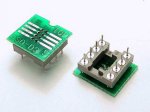
I had something more like this in mind (see attached pic).
Almosty no bigger than a 8pin DIP socket
http://www.adapt-plus.com/products_html/sol_dip/PA-SOD3SM18-08.html

I think I can make my own with some protoboard and pins to plug directly into an existing 8-pin DIP socket.
 

Attachments

Last edited:

BCJKiwi

Senior Member
Well I guess that is the penalty to be paid for a low cost single sided board without the pins!

The Adapt-Plus looks good but 8x the $!

I wondered if it would be possible to take a machined socket, insert some bent pins and solder the smd direct to the the bent pins - no board required. This should work for 8 pin at least but not for larger pin counts.

This socket could then be soldered to the board or inserted into another socket which was soldered into the board.

A potential issue with the .300" smd parts is that the legs are at the same spacing (across the chip) as the narrow Dip creating an issue for the pins if they come thru the board (which they should for strength) - spacers etc required.
 

westaust55

Moderator
SOIC8 to DIP8 adapters

here (attached) is a home brew SOIC8 to DIP8 adapter arranagement.
Note that they have rotated the IC through 90 degrees due to the pin/leg spacing issue you mentioned.

But that aside, my first endeavour will be more along the lines that BCJKiwi has mentioned with some protoboard to secure the pins
 

Attachments

Last edited:

westaust55

Moderator
SIOC8 to DIP8 adaptors

Hi eclectic,

The US$17.37 for an 8-pin surface mount to DIP adaptor pcb unassembled makes even the US$4.00 for the compact fully assembled unit per the pic I uploaded at post 17 look darned good value.

The $0.50 large PCB only unassembled that BCJKiwi mentioned looks good compared to the pic at post 19 where the guy wants US$3-00 each just for a home-made PCB that would get lost in an envelope.
 

BCJKiwi

Senior Member
Thanks for the references.
The DS1337U+ would cost almost NZ$20 landed in NZ then there is an adapter to add.

The crystals would cost over 5GBP with freight inside the UK and I would have to get a quote for NZ. From digikey the freight alone starts at US$39 to NZ.
I guess this helps to show what I'm up against trying to do some basic stuff here.
 

BCJKiwi

Senior Member
Farnell NZ is simply a website. All stock and distribution is out of Australia and have a minimum freight charge of $10 + GST (VAT).

Have an account with Farnell but only buy from them if the product value is worth the freight.

Also buy from RS who don't charge freight and do have a trade counter and basic stocks near by. However they don't carry the DS1337 but do carry the 1302, 1307 and a few others which are not relevant to this exercise.

RS also carry 14 different watch crystals but every one is 12.5pF!
 

hippy

Ex-Staff (retired)
Surf the Philips Web site. They invented the I2C and have some info there that may shed more light on the matter.
The Philips I2C Specification can be found here ...

http://www.nxp.com/acrobat_download/literature/9398/39340011.pdf

"As Standard-mode devices, however, are not upward compatible, they should not be incorporated in a Fast-mode I2C-bus system as they cannot follow the higher transfer rate and unpredictable states would occur".

The best way to handle fast and slow speed devices on the same bus is to run the PICAXE SDA/SCL to the high speed devices then run SDA/SCL to the slow speed devices via a software controlled switch. When doing fast speed comms the slow speed devices are isolated and see no bus activity so will not interfere with the bus, when doing slow speed comms the fast devices can handle that so won't interfere anyway.

Other than using a software controlled switch to completely separate the bus halves, it should be possible to blind the slow devices into not seeing bus activity by forcing the SCL input high - No "Start Bit" and the device should never do anything. That might be achievable using nothing more than diodes and resistors and some simple hard-wired logic should do the trick.
 

westaust55

Moderator
BCJKiwi,

Just had a look but Farnell Australia seem only to be in Sydney from website.
Wrong side of the country from me to drop in to the trade counter for you.

RS Components have an outlet here in Perth. They are even open on a Sat morning. But as you say, they do not have what you are looking for.
 

BCJKiwi

Senior Member
Thanks very much for your help. At this time I waiting on the last re-order and hope it will arrive very soon.

If not I will try to source the alternative version of the DS1337 with inbuilt crystal from somewhere.

As they say, patience is a virtue but do I really need to be this virtuous?
 

Michael V

Senior Member
Sparkfun

I just purchased an I2C Capacitive sensor board from Sparkfun, and it was only $4 in postage from the US to Sydney. I guess that is because it would fit in an envelope.

Sparkfun also have compact SOIC breakout boards for $3, but no DS1337. I have purchased the breakout boards for the xBee modules (to change the weird Pin spacing, and not commit them to a project) and they are good.

If you only want small quantities of small things, sparkfun are worth a look. I even purchased on line via Paypal.
http://www.sparkfun.com/commerce/product_info.php?products_id=497

Regards
Michael
 

BCJKiwi

Senior Member
Michael,
Thanks for that. It looks like they have changed their shipping methods to include USPS which gives the $4 rate. Unfortunately, they don't have the clock or crystal I'm looking for.
 

BCJKiwi

Senior Member
For those of you assisting in my quest for DS1337s and 6pF crystals;

Have established that Futurlec are currently stocking the DS1337C# RTC clock chip which is only available in SMD and incorporates the crystal.

Have also established that the overall length of one of these 16 pin SOICs pretty much matches the length of an 8pin DIP socket.
The overall width also pretty much matches the width of an 8pin DIP socket.
As the crystal is built in the grounding etc issues associated with the external crystal are eliminated.

There are also only 6 pins to deal with all at one end, 3 per side.
So the plan is to solder these pins directly to the tops of the pins on an 8 pin machined DIP socket. The space between the dip socket tops is around 0.95mm and the space between the legs on the DS1337C# is 1mm so with correct positioning this will work. Pins 1 and 3 soldered directly, pin 2 looped around to leg 3 on the socket. All other pins are NC

Will also solder down a couple of the NC pins at the other end of the 16 pin SOIC for support.

This makes a DS1337C# RTC 16 leg SOIC into an 8 pin DIP RTC.

Will provide a photo in a week or so once parts received and are soldered up.

Thanks again for your assistance and apologies for hijacking this thread which was not intended.

Cost is AU$1.56 per DS1337C# plus AU$4.00 for shipping, delivery a week or so - ordered 2 plus some 8 pin machined sockets.
 
Last edited:
Top