I want to detect the presence of DC while ignoring audio signal AC

wapo54001

Senior Member
The task is to build a Picaxe-based speaker protection circuit for a high powered amplifier. The Picaxe would provide a startup delay in connecting the amp to the speakers and then, once connected, monitor the signal path to the speaker and ignore any AC signals but instantly disconnect the speaker if DC above a certain level is detected.

I can do this except I don't know how to detect DC and ignore AC (audio signal) on the same circuit so that I can sense a fault in the amplifier and disconnect the speaker without interfering with the audio. Can I do this in software, or does it require hardware?
 

inglewoodpete

Senior Member
Doing it in software would require sampling, adding and averaging. This process all takes time. While it could work, you need to look at any delay and whether your speakers can survive this delay. And a question: how many speakers are you prepared to damage during testing?

A low pass RC filter is normally used. Of course, this can also introduce a delay. You should be able to find hardware-only speaker protection circuits on-line. Electronic magazines periodically publish projects for this sort of thing.
 

PhilHornby

Senior Member
once connected, monitor the signal path to the speaker and ignore any AC signals but instantly disconnect the speaker if DC above a certain level is detected.
How about:

Bridge rectifier + voltage divider + 5.1V Zener => Picaxe Comparator. Picaxe out drives Relay via suitable transistor. ❓

You could make use of a manual Preset to set the voltage to the other Comparator input, or you could use the FVR/DAC to do it in software (See this project).
 

AllyCat

Senior Member
Hi,
... ignore any AC signals but instantly disconnect the speaker if DC above a certain level is detected.
I can do this except I don't know how to detect DC and ignore AC (audio signal) .....
You cannot "instantly" detect a fault, because any output voltage between the supply rails could be an ac transient (i.e. the audio signal) not an "offset" dc bias level. If the output voltage is within (say) 1 or 2 volts of the supply rail(s) then a failed output transistor might be assumed, but it could still be a brief ac (overload) signal (such as a crash of cymbals). Certainly, overloading the output stage is acoustically "bad", but so is disconnecting the loudspeaker. Therefore, reducing/limiting the amplifier gain is generally a preferable method in this case.

Thus, you can only detect the presence of "dc" after a time delay, which can be implemented either by using hardware (e.g. a low-pass R-C filter) or by software (which gives many more possibilities for "intelligent" detection). But first, we must consider the type of Power Output configuration that the amplifier is using. There are many possibilities but we can consider three broad types:

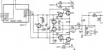
A "single output, single supply" amplifier will typically have a 50 (or perhaps 100) volt supply rail with an output (dc) bias of (approximately) half that voltage. A very large Output Coupling capacitor blocks the dc which will generally protect the loudspeaker(s) from a "dc fault". But a very low audio frequency could still overheat the "woofer" voice coil, or a full amplitude high frequency signal can certainly destroy a "tweeter". If you do wish to add additional protection, then you will need to decide on which side of the coupling capacitor you're going to connect the PICaxe ADC input (and how).

But there are numerous problems when using a large output coupling capacitor, so high power amplifiers often use Positive and Negative supply rails, such that the output bias voltage can be close to "earth" potential (i.e. zero volts). Now, a "continuous" large output voltage (positive OR negative) might be applied to the loudspeaker(s) if a fault occurs, so a protection system is indeed wise. The PICaxe ADC will of course need to be able to monitor both positive and negative voltage levels (relative to Earth).

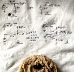
A third output configuration is the "(H) Bridge" which uses two output stages (i.e. at least 4 transistors) to drive both sides of the Loudspeaker(s) with opposite phase signals (i.e. one inverted relative to the other). This configuration is particularly useful in Lower Voltage / High Power (e.g. car audio) and/or "Class D" (switching mode) systems, because it needs neither a coupling capacitor nor multiple (+/-) Power Supplies. Of course a (PICaxe) protection circuit will need at least two ADC inputs. A class D amplifier where the Loudspeaker (inductance) is used as the primary Low Pass filter (to remove the PWM switching signal) is the only configuration which will definitely need an external R-C Low Pass filter on the ADC inputs, but a few millisecond time constant filter will probably enhance any of the above configurations.

The degree and sophistication of a protection system will depend on the magnitude of the available power level (relative to the capabilities of the Loudspeakers) and/or if very Low or High Frequencies are contained within the desired Audio Spectrum. But IMHO a "software" solution can "tailor" the protection much better to the capabilities of the Amplifier/Loudspeaker combination than a basic hardware design. The primary cause of damage is of course overheating, which is a function of time, voltage and current, noting that the Loudspeaker (voice coil) is not simply resistive, but may have a significant inductive (i.e. non dissipating) element. In principle, the PICaxe could monitor both the voltage and current levels and compute an accumulated power/heating stress. :)

Cheers, Alan.
 

wapo54001

Senior Member
Yipes. I was asked by someone on diyaudio to modify a picaxe-controlled delayed on, instant off, preamp circuit to sense an amplifier fault and disconnect the speakers. I can see that the fault signal needs to be designed into the amplifier circuit in a way that my circuit can respond to it. No such thing as a universally adaptable sensing circuit for a power amp with instantaneous response, I think.
 

fernando_g

Senior Member
In another forum, there is a schematic for a DC protection circuit in an audio amplifier.
The circuit is from an old, all-discrete transistor Marantz power amplifier.

Let me find it again and post it here.
 

fernando_g

Senior Member
As you can see, relay K2 is connected to the power amp’s output. R51 and C35 low-pass filter the audio signal which will under normal conditions average to zero.
But under a fault condition the DC voltage would build up until it is sufficient to activate the relay, which would open its contact.
Clearly the “secret sauce” here is in the relay’s pickup and dropout voltages, and it would not surprise me if this is a custom made device.

Therefore for your requirements, you would instead feed this signal into an ADC port, and select in the software the exact threshold you would like to trigger.
It is important to note that the output voltage of a power audio amp is enough to damage the Picaxe, and as such you MUST USE a voltage divider to scale the signal down.
Another important consideration is that the audio output can swing negative. A way around this is to power the Picaxe from a dedicated +/-2.5V supply.
Another would be to use opamps as an absolute value converter, providing positive voltages regardless of polarity. Or you could use a bias to shift upwards the error signal to accommodate the 0 to 5V range. But this would be a little more complex.
25784
 

wapo54001

Senior Member
Thank you for this example -- it helped a lot to understand the essentials of the problem. Dealing with a negative voltage seems to be what makes this so complicated. I need to think about this.
 

fernando_g

Senior Member
No worries, mate. The analysis is basically DC superposition and can literally be done in a napkin while enjoying a chocolate chip cookie: 25787

I am assuming that the amplifier can output +/- 50 volts.
A different range would require different values but is exactly the same analysis
 
Last edited:

inglewoodpete

Senior Member
No worries, mate. The analysis is basically DC superposition and can literally be done in a napkin while enjoying a chocolate chip cookie: View attachment 25787

I am assuming that the amplifier can output +/- 50 volts.
A different range would require different values but is exactly the same analysis
Love it! I hope it was washed down with a nice cup of Brazillian coffee.
 

julianE

Senior Member
How often do people blow speakers, I have a pair I bought in 1981, played pretty much daily and never even blew a fuse. I'm assuming fuses are no longer audiophile approved, my speakers have a single fuse that goes to a Peerless tweeter. I did replace the fuses as preventative maintenance probably 20 years ago. BTW, the speaker is mated to a Yamaha amp from 1981, it's been on continuously since new. It did have an issue with a balance pot back in the 90s otherwise it's been perfect. Hopefully the electrolytic caps are still good, it's dead silent so I'm assuming they are.
 

tmfkam

Senior Member
How often do people blow speakers, I have a pair I bought in 1981, played pretty much daily and never even blew a fuse. I'm assuming fuses are no longer audiophile approved, my speakers have a single fuse that goes to a Peerless tweeter. I did replace the fuses as preventative maintenance probably 20 years ago. BTW, the speaker is mated to a Yamaha amp from 1981, it's been on continuously since new. It did have an issue with a balance pot back in the 90s otherwise it's been perfect. Hopefully the electrolytic caps are still good, it's dead silent so I'm assuming they are.
I too have not had any problems with blown speakers due to failure of the output stages. After working with audio products for far too many years, I would find that failure of one output transistor is followed (within a few nano seconds) by failure of ALL output transistors - leading to failure of the power supplies (fuses hopefully). As all the output transistors are generally DC coupled to one another, they don't like any inbalance in the bias and all go POP! Most driver damage I've seen has been caused by excessive volume leading to excessive distortion resulting in excessive heating of the driver coils.
 

wapo54001

Senior Member
I hang out with DIY audio amateurs. The request for this item came from someone who was aware of my line-level start-delayed and instant-off preamp relay. He thought that this 08M2 based circuit could easily be adapted for power amp output control. Turns out not to be the case, and I probably won't pursue it because at this point in life I need to be selective in how I spend my time.

We audio amateurs tend to have more amplifier failures because we don't leave them alone but rather constantly modify them or swap them in and out of our systems trying other equipment for better/different sound. So, likelihood of failure is much higher and also, we love power. My main amplifier is 300 true watts per channel and a failure with DC output could destroy practically any speaker however power-hungry they are in operation.

And I do hear sad stories of expensive speakers damaged this way so the need is there. Problem is, not to many relays that can handle the kind of power that class-D has brought to the table. I saw an interesting design that used triacs (I think) to instantly open the circuit between the speakers and ground rather than opening high side to speakers with relays.
 
Last edited:

julianE

Senior Member
Audio amateurs tend to have more amplifier failures because we don't leave them alone
A few decades ago I did buy an audiophile amplifier, back breaking heavy. It's the only amplifier of many I've owned that blew the output stage. Seems like the more expensive an amplifier, the greater the chance of failure.

this point in life I need to be selective in how I spend my time
Can't agree more. As much as I listen to my hi fi I also attend many live concerts. If I had the freedom I would travel the world in order to hear all the finest orchestra. I envy our European friends, the best orchestras are a few hours away.
 

wapo54001

Senior Member
A few decades ago I did buy an audiophile amplifier, back breaking heavy. It's the only amplifier of many I've owned that blew the output stage. Seems like the more expensive an amplifier, the greater the chance of failure.
I would say instead, "the more expensive the amplifier, probably the greater voltage/current capacity and thus the greater likelihood of speaker demise in the event of amplifier failure." In the days of class AB amps you could guess the output power of an amplifier by weighing it on a scale. Not any more.:)
 

wapo54001

Senior Member
It looks like class D is accepted by audiophiles, color me shocked.
Top-end class-D offers some of the cleanest amplification out there now. Still, many audiophiles prefer the audible 2nd harmonic distortion introduced by tubes (valves). I myself use a valve preamp with user-adjustable harmonic distortion -- selectable from mostly 2nd to minimal to mostly 3rd -- to add "musicality" to my class-D power amp . . .
 
Last edited:

julianE

Senior Member
The audiophile business is fascinating class D acceptance boggles the mind but it's nothing new there was a fancy amplifier that used a national semi chip and charged a premium price. I remember when Carver first used a switching power supply and it was accepted who knows if it is now.
The part I'm most fascinated by is how brands that would never sell in boutique audio stores like Pioneer, Technics or Kenwood are the ones that were doing cutting edge work and are still in service while the 'posh' ones are long dead. I do value a well engineered and great sounding audio equipment but so much of the business end of it is a confidence game.

a valve preamp with user-adjustable harmonic distortion -
I too have a bunch of valve equipment and swore that it made a big difference then I went and made an A/B box to compare the difference between transistor and valve preamps, the difference, if any, was very slight and I could not judge which one was better. On the plus side the glowing tubes do look very cool.
 

fernando_g

Senior Member
Not too long ago someone designed an IC that would recreate “the warmth of tube sound”. Not sure what happened to that company.
 
Top