I thought this would be easy for me, but I was wrong!

regpye

New Member
This is a simple project, I thought, but I have run into trouble again.
The board has been made already so I am committed to using the pins that are in the code.
The board uses a 18M2 chip, 6 power mosfets and has 6 switched inputs and an LDR that wont be used.
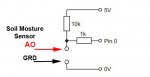
I have attempted the code to use 5 soil moisture sensors with digital outputs to give the signals to the input pins.
The mosfet outputs will activate 5 small pumps to deliver water to plant pots as required.
I added a timing sequence to the 6th mosfet to enable it to be off for about an hour and then on again for about 40 seconds, this wlll power the soil moisture sensors for only short periods of time to reduce the corrosion to the sensors.

The problem that I have found is that although all parts work, the do loops hold on when one is activated and will not allow the others to be checked until it has cleared, I need all the sensors to check at the same time because of the power on state for the sensors by the 6th mosfet.

Code:
; *******************************
;    Written by:
;    Function: Test moisture content of soild and if low turn on pump.       
;    Target PICAXE:   18M2
; *******************************

;Outputs
; B.0, B.1. B.2, B.3, B.4, B.5 these are all mosfets

;Inputs
; C.0, C.1, C.6, C.7, B.6, B.7 these are all switched or digital inputs
; C.2 ADC LDR input

; LDR not used in this program.

; 5 inputs to be used for soil moisture sensors with digital output.
; 5 mosfets used to control 5 pumps.
; 1 mosfet to be used to power the soil sensors at regular intervals.

; To save the corrosion of the soil sensors the sampling will be made for a short time several times a day, otherwise the power will be off to the sensor.

Main:
symbol sensor1 = C.0
symbol sensor2 = C.1
symbol sensor3 = C.7
symbol sensor4 = C.6
symbol sensor5 = B.6
; B.7 spare input
symbol pump1 = B.0
symbol pump2 = B.1
symbol pump3 = B.2
symbol pump4 = B.3
symbol pump5 = B.4
symbol sensorpower = B.5 ; switch on power to sensors when testing soil.


soiltest:
gosub powersensor
do
if pinC.0 = 0 then exit 
high pump1
loop while pinC.0 = 1
low pump1
do
if pinC.1 = 0 then exit 
high pump2
loop while pinC.1 = 1
low pump2
do
if pinC.7 = 0 then exit 
high pump3
loop while pinC.7 = 1
low pump3
do
if pinC.6 = 0 then exit 
high pump4
loop while pinC.6 = 1
low pump4
do
if pinB.6 = 0 then exit 
high pump5
loop while pinB.6 = 1
low pump5
goto main

powersensor:

; NOTE values have been reduced with a ; to speed up for testing purposes

; Routine for powering soil sensors.
Low sensorpower ; sensor power is off
for b0 = 1 to 2;00 ; define loop for 200 times
pause 5;000 ; wait for 20 seconds giving total of about 1 hour before turning on again.
next b0 ; end of loop
high sensorpower ; switch on output B.5
for b1 = 1 to 2;0 ; define loop for 20 times
pause 5;00 ; wait for 2 seconds total of about 40 seconds to test for moisture content on all sensors
next b1 ; end of loop
return
 
Last edited:

Buzby

Senior Member
Replace the 'do loops' with 'if else then' .

Like this ....

Code:
soiltest:
gosub powersensor

if pinC.0 = 0 then
    Low pump1
else
    high pump1
endif

if pinC.7 = 0 then
     low pump3
else
    high pump3
endif

:
: other pumps similar
:
 

regpye

New Member
soiltest: gosub powersensor if pinC.0 = 0 then Low pump1 else high pump1 endif if pinC.7 = 0 then low pump3 else high pump3 endif
Thanks for that Buzby, it is working fine now. I guessed it would be something simple.
 

AllyCat

Senior Member
Hi,
high pump1
loop while pinC.0 = 1
The instruction loop while pinC.0 = 1 (or an IF ... THEN .. ELSE) requires that the sensor is powered ON, but the subroutine had turned it OFF. So you need to power the sensors until after the instruction low pump5 , then introduce the "one hour delay" before the goto main .

This means that the sensors need to be powered all the time that any of the motors are running. But if you don't want to do that, then you need to change the structure of the program: You could read the (present) state of the sensors with for example b0 = pinsC and then power them down. Then run each motor in the main loop for a short period of time (perhaps one minute) if the corresponding sensor was "dry" with for example:
Code:
if bit0 = 1 then   ; Read sensor 1 status from b0
  high pump1
  pause 60000      ; Pause for milliseconds
  low pump1
endif
if  bit1 = 1 then
  high pump2
; etc.
Then power up and test the sensors again, until they are all reading zero (perhaps using b0 = 0), then introduce the "one hour" delay.

Cheers, Alan.
 
Last edited:

regpye

New Member
This means that the sensors need to be powered all the time
Thanks for you input AllyCat
Having the sensors powered on all the time is the problem I am trying to avoid because of the corrosion problem when the sensors are powered on.
I need all the sensors to read their readings at the same time and if a value =1 then the corresponding pump to be turned on until that sensor reads a 0.
So there are 5 sensors and 5 pumps, and anyone of them could need to be turned on during the short time that all the sensors are powered on.
Using the code change sent by Buzby is working OK, but seems a bit slow in reacting when in simulation mode. I don't feel that should be a problem because this is not a high accuracy project.
I also think that my timing of 1 hour is too close and maybe I would change that to 2 or even 3 hours or more.
I might have to also change the on timing to be a little longer too, as I am not sure at this stage how long it will take to water the pots enough.
 

regpye

New Member
I made some changes and it seems to work much better now.
A problem I found was using the gosub, and when using the real times it would stop the processing until it had timed out, so I went to bed and thought about it and made some changes and it is working fine now.

Code:
; *******************************
;    Written by:
;    Function: Test moisture content of soild and if low turn on pump.        
;    Target PICAXE:   18M2 
; *******************************

;Outputs
; B.0, B.1. B.2, B.3, B.4, B.5 these are all mosfets

;Inputs
; C.0, C.1, C.6, C.7, B.6, B.7 these are all switched or digital inputs
; C.2 ADC LDR input

; LDR not used in this program.

; 5 inputs to be used for soil moisture sensors with digital output.
; 5 mosfets used to control 5 pumps.
; 1 mosfet to be used to power the soil sensors at regular intervals.

; To save the corrosion of the soil sensors the sampling will be made for a short time several times a day, otherwise the power will be off to the sensor.

Main:
symbol sensor1 = C.0
symbol sensor2 = C.1
symbol sensor3 = C.7
symbol sensor4 = C.6
symbol sensor5 = B.6
; B.7 spare input
symbol pump1 = B.0
symbol pump2 = B.1
symbol pump3 = B.2
symbol pump4 = B.3
symbol pump5 = B.4
symbol sensorpower = B.5 ; switch on power to sensors when testing soil.

; Routine for powering soil sensors.
high sensorpower ; switch on output B.5
for b1 = 1 to 20 ; define loop for 20 times
pause 500 ; wait for 2 seconds total of about 40 seconds to test for moisture content on all sensors


soiltest:


if pinC.0 = 0 then
    Low pump1
else
    high pump1
endif

if pinC.1 = 0 then
    Low pump2
else
    high pump2
endif

if pinC.7 = 0 then
     low pump3
else
    high pump3
endif

if pinC.6 = 0 then
    Low pump4
else
    high pump4
endif

if pinB.6 = 0 then
    Low pump5
else
    high pump5
endif
next b1 ; end of loop
Low sensorpower ; sensor power is off
for b0 = 1 to 400 ; define loop for 400 times
pause 5000 ; wait for 20 seconds giving total of about 2 hours before turning on again.
next b0 ; end of loop    
goto main
 

hippy

Technical Support
Staff member
Given that you are simply setting the pump output low when the sensor input is low, otherwise high, you could simplify that part of the code with something like -
Code:
symbol sensor1 = C.0 : symbol sensor1_pin = pinC.0
symbol sensor2 = C.1 : symbol sensor2_pin = pinC.1
symbol sensor3 = C.7 : symbol sensor3_pin = pinC.7
symbol sensor4 = C.6 : symbol sensor4_pin = pinC.6
symbol sensor5 = B.6 : symbol sensor5_pin = pinB.6

symbol pump1   = B.0 : symbol pump1_pin   = pinB.0
symbol pump2   = B.1 : symbol pump2_pin   = pinB.1
symbol pump3   = B.2 : symbol pump3_pin   = pinB.2
symbol pump4   = B.3 : symbol pump4_pin   = pinB.3
symbol pump5   = B.4 : symbol pump5_pin   = pinB.4

Input  sensor1, sensor2, sensor3, sensor4, sensor5
Output pump1,   pump2,   pump3,   pump4,   pump5
Do
  ...
  pump1_pin = sensor1_pin
  pump2_pin = sensor2_pin
  pump3_pin = sensor3_pin
  pump4_pin = sensor4_pin
  pump5_pin = sensor5_pin
  ...
Loop
But I am not convinced what you have is what is actually required in practice.

You are only checking the sensors and turning pumps on or off every two hours so there's a risk of a two hour delay before watering plus potentially two hours of over-watering.

I thought the original intent was to start watering each pot as soon as it became dry and to water it for a fixed time period, and then perhaps until it no longer reported being dry.

It would help if you could define what functionality you would like to have before embarking on a solution to achieve that.
 

hippy

Technical Support
Staff member
Having the sensors powered on all the time is the problem I am trying to avoid because of the corrosion problem when the sensors are powered on.
Can you provide details or a link to what sensors you are using ?

I am no expert but my understanding of simplistic water sensors is they will corrode when wet if left powered off or only have a DC current passed through them, that the technique to prevent corrosion was to power them up and ensure an AC current whenever wet.
 

The bear

Senior Member
@regpye, Quote; Thanks for that Buzby, it is working fine now. I guessed it would be something simple.
In my experience or lack of it, nothing is simple, unless you are very familiar with programming like the people that have just helped you.
There is usually a Gotcha waiting in the wings.
I'm following your posts, they are interesting and educational projects.
It's very rewarding when something works as expected.
Keep up the good work. Don't have nightmares.
Good luck............
 

regpye

New Member
You are only checking the sensors and turning pumps on or off every two hours so there's a risk of a two hour delay before watering plus potentially two hours of over-watering.
I am assuming that the sensor circuit will do most of the work as the digital output would change from 0-1 or 1-0 depending on the moisture reading. I am stuck with using digital instead of analogue because the boards are pre-made and are not suitable for analogue. Checking the code in simulation it appears to do what is needed.

I have re-worked the code a little and in simulation it works fine, this is what I have ended up with.
I have increased the timing quite a bit as I believe that the watering will not be needed very often even in hot weather.
I also increased the power on time in order to give the pumps adequate time to do their job.

Code:
; *******************************
;    Written by:
;    Function: Test moisture content of soil and if low turn on pump.        
;    Target PICAXE:   18M2 
; *******************************

;Outputs
; B.0, B.1. B.2, B.3, B.4, B.5 these are all mosfets

;Inputs
; C.0, C.1, C.6, C.7, B.6, B.7 these are all switched or digital inputs
; C.2 ADC LDR input

; LDR not used in this program.

; 5 inputs to be used for soil moisture sensors with digital output.
; 5 mosfets used to control 5 pumps.
; 1 mosfet to be used to power the soil sensors at regular intervals.

; To save the corrosion of the soil sensors the sampling will be made for a short time several times a day, otherwise the power will be off to the sensor.

Main:
symbol sensor1 = pinC.0
symbol sensor2 = pinC.1
symbol sensor3 = pinC.7
symbol sensor4 = pinC.6
symbol sensor5 = pinB.6
; B.7 spare input
symbol pump1 = B.0
symbol pump2 = B.1
symbol pump3 = B.2
symbol pump4 = B.3
symbol pump5 = B.4
symbol sensorpower = B.5 ; switch on power to sensors when testing soil.

; Routine for powering soil sensors.
high sensorpower ; switch on output B.5
for b1 = 1 to 80 
pause 1500 ; wait for moisture content reading on all sensors

if sensor1 = 0 then
    Low pump1
else
    high pump1
endif

if sensor2 = 0 then
    Low pump2
else
    high pump2
endif

if sensor3 = 0 then
     low pump3
else
    high pump3
endif

if sensor4 = 0 then
    Low pump4
else
    high pump4
endif

if sensor5 = 0 then
    Low pump5
else
    high pump5
endif

next b1 ; end of loop
Low sensorpower ; sensor power is off
for b0 = 1 to 240 ; define loop for 4 hours
wait 60  ; wait for 60 seconds giving total of about 4 hours before turning on again.
next b0 ; end of loop    
goto main
 

Buzby

Senior Member
Here is how I would do it.

The loop runs once per second, and all timers and intervals are derived by counting these seconds.
This means it's much easier to monitor whats going on, as you can watch each timer counting.
( I know this is not an accurate method of timing, but it's OK for this application. Using the 'time' variable would be lots more accurate. )

The sensors are read every 30s, ( obviously you will set this higher, e.g. 14400 sec = 4 hours )

When the sensor are read, any pumps needed to run are started. Each pump has it's own timer, and will run until it's timer expires.
This allows each pump to run for different times, maybe 1 or 2 minutes. In this demo they are all set to 10 sec.

Code:
; *******************************
;    Written by:
;    Function: Test moisture content of soild and if low turn on pump.       
;    Target PICAXE:   18M2
; *******************************

;Outputs
; B.0, B.1. B.2, B.3, B.4, B.5 these are all mosfets

;Inputs
; C.0, C.1, C.6, C.7, B.6, B.7 these are all switched or digital inputs
; C.2 ADC LDR input

; LDR not used in this program.

; 5 inputs to be used for soil moisture sensors with digital output.
; 5 mosfets used to control 5 pumps.
; 1 mosfet to be used to power the soil sensors at regular intervals.

; To save the corrosion of the soil sensors the sampling will be made for a short time several times a day, otherwise the power will be off to the sensor.


symbol sensor1 = PinC.0
symbol sensor2 = PinC.1
symbol sensor3 = PinC.7
symbol sensor4 = PinC.6
symbol sensor5 = PinB.6
; B.7 spare input
symbol pump1 = B.0
symbol pump2 = B.1
symbol pump3 = B.2
symbol pump4 = B.3
symbol pump5 = B.4

symbol SoilDry1 = bit1
symbol SoilDry2 = bit2
symbol SoilDry3 = bit3
symbol SoilDry4 = bit4
symbol SoilDry5 = bit5

symbol mem1 = bit9
symbol mem2 = bit10
symbol mem3 = bit11
symbol mem4 = bit12
symbol mem5 = bit13

symbol tim1 = b4
symbol tim2 = b5
symbol tim3 = b6
symbol tim4 = b7
symbol tim5 = b8
symbol timR = w5

symbol sensorpower = B.5 ; switch on power to sensors when testing soil.

do
    pause 1000 ' Run loop every 1000mS.
'This is the timebase for all other intervals and timers.

' Sensor time interval    
    if timR = 0 then ' If sensor timer = 0 
        timR = 30  '  Reset interval for sensor reads
        gosub ReadSensors
        mem1 = 0 '
        mem2 = 0 '        
        mem3 = 0 '    Reset pump start memories    
        mem4 = 0 '        
        mem5 = 0 '
      else
        dec timR ' If time not zero, decrement it
    endif
    
' Pump 1 control
    if SoilDry1 = 1 and mem1 = 0 then
        tim1 = 10 ' Run time for pump
        mem1 = 1  ' Memory for pump started
    endif
    
    if tim1 > 0 then ' If timer running
        high pump1 '  run pump
        dec tim1   '   decrement timer
    else             ' If timer elapsed
        low pump1  '  stop pump 
    endif

' Pump 2 control
    if SoilDry2 = 1 and mem2 = 0 then
        tim2 = 10 ' Run time for pump
        mem2 = 1  ' Memory for pump started
    endif
    
    if tim2 > 0 then ' If timer running
        high pump2 '  run pump
        dec tim2   '   decrement timer
    else             ' If timer elapsed
        low pump2  '  stop pump 
    endif    

' Pump 3 control
    if SoilDry3 = 1 and mem3 = 0 then
        tim3 = 10 ' Run time for pump
        mem3 = 1  ' Memory for pump started
    endif
    
    if tim3 > 0 then ' If timer running
        high pump3 '  run pump
        dec tim3   '   decrement timer
    else             ' If timer elapsed
        low pump3  '  stop pump 
    endif    
    
' Pump 4 control
    if SoilDry4 = 1 and mem4 = 0 then
        tim4 = 10 ' Run time for pump
        mem4 = 1  ' Memory for pump started
    endif
    
    if tim4 > 0 then ' If timer running
        high pump4 '  run pump
        dec tim4   '   decrement timer
    else             ' If timer elapsed
        low pump4  '  stop pump 
    endif        
    
' Pump 5 control
    if SoilDry5 = 1 and mem5 = 0 then
        tim5 = 10 ' Run time for pump
        mem5 = 1  ' Memory for pump started
    endif
    
    if tim5 > 0 then ' If timer running
        high pump5 '  run pump
        dec tim5   '   decrement timer
    else             ' If timer elapsed
        low pump5  '  stop pump 
    endif        
    
loop


ReadSensors:
    high sensorpower    ' Power on sensors
    pause 1000        ' Allow time for sensors to settle
    SoilDry1 = Sensor1 '
    SoilDry2 = Sensor2 '
    SoilDry3 = Sensor3 ' Read sensors. 1 = dry, 0 = wet
    SoilDry4 = Sensor4 ' 
    SoilDry5 = Sensor5 '
    low sensorpower    ' Power off sensors
return
 

Attachments

regpye

New Member
Here is some more info about the sensor and also some coding for an Arduino.
The way I understand it, the sensor will switch between high and low as required, so a specified amount of time to turn the pumps on or off would not be required as it should be automatic. (I think)
Link to another website for a similar project.
 

Buzby

Senior Member
... the sensor will switch between high and low as required, so a specified amount of time to turn the pumps on or off would not be required as it should be automatic.
Yes, and no.

The sensor will react quickly, but the Picaxe code only reads the sensors every few hours.
This means you can only change pump states every few hours.

My code reads the sensors every few hours, but uses timers to turn off the pumps.
Otherwise the pumps will run for a few hours, not what I think you need.

Regarding your sensors, if you changed to capacitive moisture sensors you would not need to use anti-corrosion timers.

Here is an example ...


Note : I take the 'corrosion resistance' of this device with a pinch of salt. The sensing element is maybe resistant, but the electronic components just a few mm away from the sensor certainly are not. How you keep that end of the device dry is up to you. ( I covered the whole board with a few coats of varnish. )

Edit : Just found this, https://www.instructables.com/Waterproofing-a-Capacitance-Soil-Moisture-Sensor/
 
Last edited:

regpye

New Member
Regarding your sensors, if you changed to capacitive moisture sensors you would not need to use anti-corrosion timers.
I am aware of this, however I purchased these resistive ones some time ago and have 24 of them, so I really would like to use them.
Also I am wondering if I could actually use analogue programming instead of digital because my board is wired up this way for the inputs.
25861
 

regpye

New Member
The sensor will react quickly, but the Picaxe code only reads the sensors every few hours.
This means you can only change pump states every few hours.
I am not sure that that is correct.
What I was trying to do was to have the sensors be power active for a few minutes and during that time the sensors should be able to determine if one or more of the pumps turn on.
Within that few minutes that pumps should have done their job as there would not be a lot of water to move and the sensor would also send a new signal back to the pin to end the need for pumping.
To make sure the pumps don't stay on, I could also send a coded signal to stop the pumps at the beginning of the off period for the sensor power.
The off period would be say 4 hours and at the end of that would repeat the cycle again and check if any of the pots needed water or not.
I could be wrong, but I have tested it in simulation mode in PE6 and it appears to work okay.
 

hippy

Technical Support
Staff member
Also I am wondering if I could actually use analogue programming instead of digital because my board is wired up this way for the inputs.
Sensor pins C.0, C.1 and B.6 can be used for analogue input, pins C.6 and C.7 cannot.

PIn C.2 is analogue but used for LDR.

You could modify or redesign the board to allow all 5 sensors to be analogue but it's probably not worth it.
 

hippy

Technical Support
Staff member
Picaxe code only reads the sensors every few hours.
The code I have written reads the sensors 80 times in a 2 minute period, that should be enough to pump a few litres of water where needed.
That's true and should work, but then you wait 4 hours before checking the sensors again, so I would consider it as Buzby says. Perhaps better said as "assesses the sensors" rather than "reads the sensors".
 

regpye

New Member
You could modify or redesign the board to allow all 5 sensors to be analogue but it's probably not worth it.
Thanks Hippy, yes you are right, I will stay with digital, the accuracy is not that important for this project.
 

regpye

New Member
but then you wait 4 hours before checking the sensors again
From my experience with these things already (plants and such) the pots are not going to dry out within a 4 hour period, I may even have them checked only once or twice a a day after testing in real life.
 

hippy

Technical Support
Staff member
From my experience with these things already (plants and such) the pots are not going to dry out within a 4 hour period, I may even have them checked only once or twice a a day after testing in real life.
True. The big picture question with any automation of a task is what one hopes to achieve, how one hopes to improve an existing situation. You can go from checking once a day and watering, so you never forget as people are inclined to do, to keeping the plants as optimally watered as they can be.

Whatever one desires can usually be implemented but what can be implemented depends on knowledge of how to and having the skills to do it.

Accepting that, it's not unreasonable to choose some implementation where one has the skills and knowledge to do it, or there's not much of a steep learning curve to get there.

So what you have seems to be a perfectly fine approach. You can get that working, see how effective it is, tweak it as needed, and go from there.
 

regpye

New Member
So what you have seems to be a perfectly fine approach. You can get that working, see how effective it is, tweak it as needed, and go from there.
Thanks Hippy, that is very encouraging.
I am no expert in coding as you will have found, but I am trying to learn, mostly by my mistakes.
When really stuck or have a brain fog, I ask here and have had a very lot of useful help in the past.
I find it a lot of fun and have made a number of useful things now that I could not have done before.
 
Top