I/R intterupt barrier

bfgstew

Senior Member
Good morning all,
I could do with some help on this barrier idea of mine please.

The concept is a barrier using I/R emitters to I/R photodiodes, now the barrier is only 350mm x 250mm and is going to be used to catch small insects, birds etc in flight by breaking the beam which is connected to an ADC channel pin, trigger level is set via a pot and when ADC reaches level this it will cause an interupt and trigger my camera.
I have seen light barriers on the market like this but obvious cost implications involved!!!!
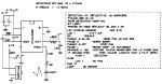
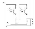
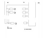
So my idea is using multiple (20)IR emitters on one side and receivers on the other to match. Now the 20 emitters is not a problem, the problem is the 20 receivers, well the final signal to the ADC pin is the problem. I have done a simulation on LIVEWIRE but with a phototransistor and with 20 in series the voltage drop is getting close to 3v and the reaction of the last receiver is poor not falling off until no light is on it. I need a good sweep on all receivers and sharp reactions from all of them.
A small diagram outlines my concept.

IR.JPG

These are the http://www.bitsbox.co.uk/data/optos/tsus5400.pdfemitters and http://www.bitsbox.co.uk/data/bp10nf.pdfreceivers I am wanting to use.

Any ideas or changes to this idea would be gratefully received.
 

rossko57

Senior Member
Could you tell us if you are seeking a simple "curtain broken" (one or more beam breaks), or need to know which beam breaks?
 

AllyCat

Senior Member
Hi Stewart,

Yes, I also think 20 phototransistors is too many. There are many other possibilities: maybe use a mirror to "fold" the beam(s), or pulse (say) 4 LEDs in sequence and monitor with a single LED (for each group).

Also consider that the phototransitors can be operated in a linear (analogue) mode (sensitive) or primarily saturated (as a switch) which will need more light. In analogue mode the transistors would probably be run "in parallel" with resistive mixing to produce an analogue voltage to be detected by a PICaxe AD input. In digital mode each transistor (in a series chain) might drop, say, 300 mV (when illuminated) but if the light level to any one drops considerably then its voltage drop could "break the chain".

Alternatively, if phototransistors are connected in reverse they become photodiodes, not as sensitive but "guaranteed" to be linear (current versus light level). If they are all connected in parallel then their combined "leakage" current will reduce a little (when any one is obstructed). Not a great current change, but probably enough to be detected by a PICaxe 10 bit AD input.

Your exact method may depend on how quickly you require the detection to work. Analogue detection is potentilly slower, but much more "controllable" than using saturated transistors.

Cheers, Alan.
 

bfgstew

Senior Member
Thanks so far chaps.

Yes Rossko57, it is a beam break curtain, doesn't matter which one. The output is monitored via ADC so if the value reaches the target value the interupt occurs.

Alan, appreciate the input and can see where you are coming from. The mirror idea is what I have at the moment but using a little laser, unfortunately, the mirror is diffusing the beam far too much and can only get 6 reflections before it becomes to weak to be picked up, also the gaps between the beams are also an issue, allowing subject to go through undetected, hence the need for 20 odd sensors.

I have had another play with livewire and have increased input voltage to 12V and I add a 100K resistor to the output of each phototransistor, I now get a reasonable value on the ADC channel, I shall have some more experimentation and see what can be done. I do need it to be as simple as possible.

12VIR.JPG

Jim, nice idea and thanks for taking the time to search for stuff, but they only have a 12mm range, I am looking at 350mm range.
 

Circuit

Senior Member
Just an added thought for the operation of such a large IR diode array; don't forget that the array, whilst invisible to the human eye, will probably be highly visible to your camera sensor. This could be the equivalent of looking into car headlamps. You may therefore wish to incorporate into your circuit a PICAXE pin-controlled off switch to switch off the diode array immediately before your camera is triggered.

With regard to the laser/mirror idea, what you need is a series of surface-reflective mirrors. Normal mirrors are glazed on the rear surface and passage of the laser beam through the glass causes your problem. Surface-coated mirrors are the answer and will reflect the beam over many iterations without loss of beam intensity or coherence.
 

AllyCat

Senior Member
Hi Stewart,

Hmm, I'm not sure how that circuit is supposed to work, or how you'd extend it to more stages. The first 100k appears to partially "short out" the second transistor, whilst the second 100k doesn't do much as it's in parallel with 10k.

If you put one (illuminated) phototranistor in series with (say) 10k across (say) 5 volts dc, what voltages do you measure across the transistor and/or resistor? The latter will give an indication of the current flow (or you could measure it directly with a multimeter). Then repeat with the light path (partially) obstructed. Those measurements will give some indication of what type of circuit to use. If the "illuminated" current is rather high (transistor saturated with a low VCE) then try reversing the Emitter and Collector connections.

How do you plan generate an "interrupt" from an A-D signal? But "polling" with a PICaxe is not very different anyway.

Also, might the IR array look like a searchlight to your "targets"? But I think it's mainly UV that insects' eyes have extended sensitivity. Or perhaps you want to attract them "like a moth to a flame" anyway?

Cheers, Alan.
 

bfgstew

Senior Member
Circuit, thanks for the pointer, the I/R emitters are or will be fully enclosed with a small 3 or 4 mm oriface for the I/R to exit so it will be shielded from the camera, and I do have in the program the off command as soon as the interupt occurs........

Nice info on the mirrors, do you have any links?
 

bfgstew

Senior Member
Just watched an instructable VID on how to make them, so I may give that a go first as it seems the quicker and cheaper option, thanks again for the pointer.
 

Circuit

Senior Member
Circuit, thanks for the pointer, the I/R emitters are or will be fully enclosed with a small 3 or 4 mm oriface for the I/R to exit so it will be shielded from the camera, and I do have in the program the off command as soon as the interupt occurs........

Nice info on the mirrors, do you have any links?
Just ask your dentist! The best dental mirrors are surface-coated. Some of the disposable dental mouth mirrors are plastic but with a non-double-reflective surface coating. The best ones are "Rhodium-coated" - your dentist may be able to source a few for you amongst his regular practice orders. Otherwise, have a look at dental supply houses - there are also larger dental photographic mirrors available. Also, the mirror in most SLR cameras is often surface-coated (lots of old film cameras are around, never to be used again); as are the mirrors in telescopes etc. Have a browse around here http://www.edmundoptics.com/products/ or just search for "optical component suppliers" for other references.
 
Top