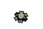
I have a 5V supply and a 3.6V max LED

Jarubell

Senior Member
I'm troubled with trying to figure out how I'm going to power a 2.8W LED that requires a max of 3.6V and 350mA. I have on my breadboard a small relay which I figure I would use to switch the LED. I have been trying to figure out a voltage divider but I'm not getting anywhere and I really don't have a clue if that would be my solution.

Jarubell
 

goom

Senior Member
The simplest method would be to add a resistor in series with the LED.
Since you need a 1.4V (5.0 - 3.6) drop across the resistor at 0.35A, the resistor needs to be 1.4 / 0.35 = 4 Ohms (from Ohm' law).
Power dissipation for the resistor will be 0.35 x 1.4 = 0.49 W, so best to use one rated at 1W or higher.
You may also wish to consider a constant current source, either home made or a ready made commercial one. Perhaps others can direct you to a suitable part or design
 

Dippy

Moderator
Some thoughts...

It's easier to think of an LED as a current device.
i.e. when you pass X Amps (or milliAmps/mA) through it then you will observe a forward voltage drop (Vf) of X volts.
Remember, it is a semi-conductor junction device.

You haven't supplied the data sheet, so based on the information; when you pass 350mA thorugh it you will observe a forward voltage drop of 3.6V - not that you must feed it with 3.6V. That's where your potential divider idea falls down.

It doesn't (per se) 'require' 3.6V, but it does mean that your supply must be greater than 3.6V for a resistive limiter.

Goom has provided the basic maths for a resistive current limiter.
Generally: I = (Vsupply - Vfled) / R from good old Ohm's Law. And rearrange to suit.
Which is OK for a constant voltage supply.
The power dissipated for the resistor and LED will be Ivy Watts or variation.

Goom also suggested a Constant Current supply - search the Internet for example circuits. Note that a voltage 'headroom' is required depending on the design.

Finally, an important other thing to think about; HEAT.
Most people erroneously think LEDs run cool. No!
Your LED (unless supplied on a purpose-built module) will require heatsinking.
A single LED soldered to your breadboard and run at full power will die in minutes.
A modern 3W LED will need a heatsink based on >2W dissipation of heat. I'd base it on the full amount.
ALWAYS consult the manufacturer's data if you actually want the LED to last more than 2 seconds.
Long LED lifetime is closely related to your heatsinking.
And Vf and brightness will be affected by the temperature. It really is important.
So, read up or link the data-sheet here so that others can advise.
 

Jarubell

Senior Member
Specs; Test Forward Current 350mA, Power Dissipation 1.1W, Forward Voltage 3.0 Min, 3.3 Avg, and 3.6 Max.

2.8W LED.jpg

I was blinded by my frustration and that formula looked extremely familiar.

I=(Vs-Vf)/R, 0.35=(5V-3.5V)/R, R=(1.5V)/.35, R=4.28ohms

So if I wanted to use two of these LEDs, I would have to put them in parallel because the combined voltage would be great than 5V in series? Would I be able to use 12V for in series?

R=(12-(3.5+3.5))/0.350mA =14.28ohms

As for the power dissipation of 1.1W (2.2W I guess for the two of them), I was going to install them in a box with a clear top, could that be a mistake?

Thank you both for the help, almost embarrassed I had to ask the question,

Jarubell
 

Goeytex

Senior Member
I think you may be misreading the specs. The "test current" is 350ma. This is not necessarily the max current or even the suggested operating current. Most 3 watt LED have a max current of up to 1 amp and can comfortably operate at 750ma with proper heat sinking. Many manufacturers test LEDs at 350ma because this is where they are most efficient (lumens per watt). In other words, the brightness is not proportional to power ( or current). An LED operating at 3 watts will not be three times brighter than one operating at 1 watt.

Consider that if the forward voltage is 3.6 and there is a current of 350ma then the LED would only be rated at about 1 watt. If the max forward voltage is 3.6 and the LED is rated at 2.8 Watts then the current would be ~ 750ma.

Better provide us a link to the datasheet, or if it is a cheap no-name LED then a link to where it was sold ( Ebay, AliExpress, etc).

Another thing to be aware of with high power LED is thermal runaway. The hotter the LED gets, the lower its resistance. With lower resistance more current flows and it gets even hotter until ................... LOUD POP! and Darkness ........
 
Last edited:

inglewoodpete

Senior Member
As for the power dissipation of 1.1W (2.2W I guess for the two of them), I was going to install them in a box with a clear top, could that be a mistake?
A metal box with a clear top would be OK. As would a vented plastic box but not a sealed plastic box. You will need some heatsinking for a 1.1Watt LED if you want long life.

Putting higher powered LEDs in parallel without individual over-current protection is asking for trouble. If one fails and goes open circuit, the other gets double the current and fails shortly afterward!

Most of my work with LEDs is 10W and higher. I would not think of operating them without a current regulator. You can usually run them short-term (< 1 minute) without a heatsink.

... almost embarrassed I had to ask the question.
There are two ways to learn. Ask questions ("research") and make mistakes! Both have their place.
 

Goeytex

Senior Member
The datasheet is one of the worst I have seen for a high power LED. It does not have an Absolute Maximum Ratings section, neither does it provide graphs or performance curves. For all practical purposes I would consider this a 1 Watt LED until proven otherwise. I don't see how Solarbotics came up with a 2.8 Watt rating. I would definitely not operate this LED above 350ma and then only with a good heat sink.

Actually I would take one and put it on a good heat sink and test it until it failed, while logging forward voltage, current, temperature & light output.

As far as a driver goes I might try one of these from Sure Electronics (Ebay). 1W LED Driver

With a 12V supply, this will drive 2 350 ma LED's at a reasonable efficiency.
 
Last edited:

Jarubell

Senior Member
Had a little lesson last night, well I think I did. I decided to run that LED from above on 12v (the plan is to run two off 12v in series but just one for now), did the math and all was well, till I let the smoke out of the resistor. Trying to figure why, I concluded that I most likely have 1/4watt resistors and if my math is right, 350mA and 3.5 across the LED, I figure 2.975watts=.35Ax8.5v. Am I on the right path? If so, when I use two of the LEDs, the 14ohm resistor will need to be greater than 1.75W?

Other than that, my PICAXE is running great with 2 inputs, temp and switch, and two outputs to transistors firing relays. Thanks for the help! Just need to get it off my breadboard.
 

Goeytex

Senior Member
Why are you using a resistor to limit current on this LED? That is the worst possible way of limiting the current and the most inefficient.

But if you insist upon using a resistor (and making a heater) Then get a 4 or 5 watt resistor like this and mount it on something that won't burn or melt. If you mount it to a metal coffee cup, using some heat sink compound, it will keep your coffee (or tea) hot.

http://www.mouser.com/ProductDetail/Vishay-Dale/RE60G15R0C02/?qs=sGAEpiMZZMvNd0dY0KymzomHUTmqNz7iPPHi4E34qJ8=
 

inglewoodpete

Senior Member
You can get current regulator circuit boards for 12v working that are the size of your thumbnail. They are so small they fit in the back of 12v LED light "bulbs". Eg the type that have 3 x 1W LEDs in them. Hobby electronics stores sell the bare regulator too. This one in Australia is overpriced but gives you an idea of what they look like. These are under $2, post free from Asia if you're prepared to wait a few weeks for delivery.
 

BESQUEUT

Senior Member
But if you insist upon using a resistor (and making a heater) Then get a 4 or 5 watt resistor like this and mount it on something that won't burn or melt.
If you are in a hury, and only have 0,5W resistors, you can also use 11 x 150 ohms (for less money, and usually easier to find ...)
 

Goeytex

Senior Member
Looks ok to me. ( Better than a resistor). However ...... with 2 LEDs in series and to reduce power dissipation ( heat) in the regulator, use a 9V supply instead of a 12V supply. You should be able to find a 9V 500ma - 1A wall wart for pocket change.
 

John West

Senior Member
You might want to look closely at the Fig.1 and Fig.2 graphs in the datasheet. They indicate that, depending on the regulator device temperature, that an "overhead" of 7 Volts or so being dropped by the device will be required to ensure 350 mA output. That means that with 7 Volts being dropped by the LED's, another 7 volts will need to be dropped by the current regulator to ensure full regulation current of 350 mA, which would mean that half your available power would be dissipated by the regulator device.

It's a "one chip solution," but if you can afford to get a small step-down switch-mode current regulator as Goeytex suggested earlier, you'll run a lot cooler and use much less energy. Switch-mode modules can control current without dissipating much energy at all, and get more efficient as the applied voltage increases.

One designed for 350 mA and a 12 V input would run 2 LED's in series just fine, and efficiently.
 
Top