I cant seem to program my picaxe

Protolisk

Member
I've been trying for a few days but I cant seem to program my picaxe.

I always get the error hardware not found on com 1. First I thought that maybe the port on the computer doesn't actually connect to anything so I changed to a laptop. neither of them worked. Then I though I had bad wires so I used alligator clips to clip in the the socket legs directly. That didn't work so I took out the pic and tried hooking it up directly but that didn't work.

I'm using 2 Duracell AA batteries to power it. I'm gonna try with 3.

EDIT
Ok it didn't work is it possible to get a dud picaxe.
 
Last edited:
you need at least 4 volt to program a picaxe

is it a new picaxe? try another one to see. On the program editor software click on options and maybe try a different port.
 

Mycroft2152

Senior Member
Which PICAXE?

Before you return it as NFG, try it with 3 AA batteries, 4.5 volts or a 5 volt power pack.

Note; Nicads are not 1.5 volts, they are more like 1.2volts.

Myc
 

Protolisk

Member
Tried with 3 AAA non rechargable batteries. Also I'm using it in an xbox controller so you can probably guess what its for. In the forums that has the tut on it everyones using the same 08M picaxe chip and it works fine for them so I'm guessing that its mine that broken.

Whats NFG stand for.
 
Last edited:

Mycroft2152

Senior Member
Its very unlikely that you got a bad PICAXe 08M.

Are you using the the 2 resistor download circuit from the manual?

I'm concerned about your comment of using clips. Post a photo if possible.

Myc

Note: the XBoX controller is a good PICAXE project. You'll get a lot of help as long as you are learniing to use the PICAXE.
 

Protolisk

Member
Well I haven't always tried it with "just" the aligator clips at the start I had it powered by the controller and it was connected to the download cable by a stereo socket.
 

manuka

Senior Member
NFG = NO ******** GOOD, which is usually more politely shown as NBG! You may want to recognize a few others while you are at it, especially FUBAR = ******** Up Beyond All Repair & SNAFU (Situation Normal All ******** UP), from the 1940s.

Anyway-most programming woes are PC or cable related- SO PLEASE DETAIL YOUR EXACT SETUP, perhaps with pictures. I've been involved with 1000's of PICAXEs since their 1982 roll out, & have NOT had a dud one yet- the little darlings are near indestructible.

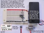
Forget about the XBox at this stage, as I STRONGLY suggest you just set up a simple 08M test bed much as shown below. I've had even 10 yo. kids here in NZ successfully make these. Stan
 

Attachments

Last edited:

Protolisk

Member
hmmm could it be the wires tthough. The tut said to use 30 gauge wires I think I have slightly smaller ones. They're from an old ps/2 mouse or whatever you call it.

Ok here's my set up.

I have my 9pin thing with
pin 2 just a wire
pin 3 a 10k resistor also connected to pin 5
pin 3 a 22k resistor then a wire
pin 5 a 10k resistor also connected to pin 3
pin 5 a wire

I know your not supposed to have them in you cable but I already built it and I heard that after you program it all you have to do is hook up the serial to ground. Also I had another one where it was made from some ear phone wires which had enamel on it so I burnt the end to get rid of it.

That goes to some less thatn 30 gauge wire which connects to the socket then to the chip.

Alligator clips later from the cable to the socket. Then afterwards to the chip and then straight from the 9pin thing to the chip.


I also had another socket which had the download cable built into it but it didn't fit in the controller as well as this one.
 
Last edited:

manuka

Senior Member
Picture(s) changed for those with sensitive dispositions- neither are mine in fact, as they're via Andrew "Brightspark", who does MEGA NZ schools PICAXE work. As already mentioned, even 10 yo's (-well- make that NEW ZEALAND 10 yo's) have found this approach lucid. Be convinced at Andrew's site => http://www.picaxe08.orconhosting.net.nz/

EXTRA: PROTOLISK:Argh- words- words- words! This is hi-tech 2008, not Shakespearian 1608. In case you haven't heard, many of us engineers are tactile (="hands on") & visual types. Although we can barely string a sentence together to save ourself, technical woes can be often analyzed via a glance or deft touch. Why I've known technicians who can make a reluctant oscilloscope sit up & dance, simply by waving their hot soldering iron over it. It's said Dippy can even persuade cosmic rays to deviate just by switching on his DMM, & the success of the recent Mars lander is due to Hippy's graveyard shift stargazing. I myself claim only modest technical charisma, & am content merely for the sun to continue shining, & have my old faithful laptop smoothly run YouTube videos. Yes- us colonials are indeed easily pleased.
 
Last edited:

womai

Senior Member
Assuming your description is correct and you did not double-count the 10k resistor, then the problem is the last (third) resistor (10kOhm between pin 3 and pin 5). Remove it and it should work fine.

Otherwise I highly recommend posting a decent picture of your connector and your setup, so others can troubleshoot it more easily.

Wolfgang
 

Protolisk

Member
yeah I double counted them. Trying to get a picture but someone used the camera and didn't charge the batteries.


What are those stars supposed to be?

F**ck**g?
And whats NBG

Ok I managed to take a picture using the webcam but it doesn't have a macro option. I was trying to take one of the socket but its too small to see it when its in focus and too blury to see it when big enough.


Last edited:

Protolisk

Member
the masking tape is there so that one wire wont make contact with the other since they were soldered closely together.

I dont think its a power supply problem cause once I connected power to the controller and turn it on and I could hear a whirring sound. Found out it came from the picaxe and it was vibrating against something making it sound louder. Another tim when it made that noise it was't touching anything but it was a lot higher pitched and softer.
 
Last edited:

hippy

Ex-Staff (retired)
It might be a silly question but are you sure it's a PICAXE and not a PICmicro ?

My recommendation would be to build a small strip-board / vero-board / bread-board setup with just the minimum connections for power and programming and get that to work before trying to get it to work within the controller.

I'd also recommend using a PICAXE which hasn't been inserted in the controller in case doing so has damaged it. Once you get one PICAXE working check all the others work so you can weed out any duds.

Also double check your wiring, that 0V and +V go to the right pins ( I'm forever getting that the wrong way round on the 08/08M ) and the same for the download connections. Make sure you haven't counted the pin numbers on the 9-way wrong, got TX and RX swapped over, or wired for a female when it should be male or vice-versa. Use the View -> Options -> Seria l-> Test menu option to check the serial wiring is correct.
 

Protolisk

Member
already tried the testing thing but my volt meter thing borke a while ago. Not sure why. Also I dont think its a PICmicro since it cost $6.
 

westaust55

Moderator
hmmm could it be the wires tthough. The tut said to use 30 gauge wires I think I have slightly smaller ones. They're from an old ps/2 mouse or whatever you call it.

Ok here's my set up.

I have my 9pin thing with
pin 2 just a wire
pin 3 a 10k resistor also connected to pin 5
pin 3 a 22k resistor then a wire
pin 5 a 10k resistor also connected to pin 3
pin 5 a wire

I know your not supposed to have them in you cable but I already built it and I heard that after you program it all you have to do is hook up the serial to ground. Also I had another one where it was made from some ear phone wires which had enamel on it so I burnt the end to get rid of it.

That goes to some less thatn 30 gauge wire which connects to the socket then to the chip.

Alligator clips later from the cable to the socket. Then afterwards to the chip and then straight from the 9pin thing to the chip.


I also had another socket which had the download cable built into it but it didn't fit in the controller as well as this one.

From the above, I take it that you are using a 9-pin to 9-pin serial cable and soldering some resistors and wired direct to the PICAXE end of the serial cable.


For pin 2 and 5 you say "pin 2 just a wire" . Where have you connected this wire. Not the clearest description.

Can I suggest that you:
1. Upload a schematic diagram of the connections
2. Upload a clear close up photo of the circuit.


Also I had another one where it was made from some ear phone wires which had enamel on it so I burnt the end to get rid of it.
Ah buring off the enamel - thats where the black stuff on the soldering iron tip comes from :rolleyes:

A very simple way to get a quick schematic is to draw it in a simple paint type program and save as a jpg file or draw in say Excel and print yusing one of the free .pdf file creators.
 
Last edited:

Protolisk

Member


Ok very quick one in photoshop.

naa my tip went black cause I didn't know you had to tin it. Also I burnt it off with a candle.
 
Last edited:

Peter M

Senior Member
hope that drawings not right? well I guess if it is that solves your problem!!:eek:

Power is backward
Pin 1 = +ve
Pin 8 =-ve
should be a 22K not a 2K2 resistor

Please DO look at manuka's pictures:D
 

BCJKiwi

Senior Member
The picture is not right.

Assuming the notch in the 08M is to the left, then
physical pin1 (leg1) is at bottom left, 2, 3, 4 along the bottom, 5, 6, 7, 8 along the top with 8 opposite 1.

Red? wire from power supply positve connects to leg 1, Black? 0V from supply goes to leg 8.

Check out the diagram in the Manual Section 1 page 22.
 

Protolisk

Member
ok still not working and I'm using a different socket. Tried both the laptop and the computer. Is there anyway of see if the PICAXE is on? like it makes a sound it heats up?

Still using the webcam to take pics
 
Last edited:

Dippy

Moderator
Proto, I suggest you stop right there, stand back and look at what you are doing.

Goodness knows what that photo is trying to show us. I know what it shows me.

Your drawing is all back to front. Frankly, I don't know whether your drawing is wrong, wiring is wrong, whatever.

PLEASE:-
LOOK at the 08M drawing in the Getting Started Manual No.1.
LOOK at the pin/leg numbers and then compare it to your drawing.
Maybe you drew your picture from the underside, who knows?

Judging by what you have shown us so far it AIN'T the PICAXE at fault, sorry.

"i thought positive goes to negative."
-IDKWTS. Positive/+ve SUPPLY goes to the PICAXE chip pin marked POSITIVE/+ve. For the NEGATIVE/-ve/Gnd/0V line well, cough, that goes to the pin marked NEGATIVE/-ve/Gnd/0V.

"Is there anyway of see if the PICAXE is on? like it makes a sound it heats up?"
- Well, if you connect it wrong or use a too high voltage it will heat up and probably make a noise like BANG!!
If you have connected it correctly you should see a few milliamps load.
(Are you being serious here btw? Or taking the Mick?)

Start again. Be tidy and methodical. And if it doesn't work, I really wouldn't start blaming a duff PICAXE.

When you order a replacement 08M PICAXE also get the cheapest little 08M Project Board you can.
If you have connected it correctly you should see a few milliamps load.
Have you got a Multimeter/Ammeter that can measure in the milliamp (mA) range?

Have you got a teacher at school that can help with this as it sounds like you are having a bit of trouble with the real basics??
 
Last edited:

manuka

Senior Member
Well said Dippy. It's a nice photo of the carpet,but I also can't follow anything else in the picture...
 

Protolisk

Member
Sorry the battery for the camera hasn't fully charged yet so I had to use the webcam. Yeah I drew the picaxe from the underside. Thats what keep referering to it to be like in the xbox tut I'm following. Sorry a habit.

Was confused about the negative positive thing cause normally with batteries the positive end goes to the negative so I thought it was the same for everything else.

yeah cause mine was making noises and was a little warm before.

I dont have a volt meter or anything like that.

The only electronics stuff I've done before was for less than a term in science in year 8, last year.
 

westaust55

Moderator
Have you got a Multimeter/Ammeter that can measure in the milliamp (mA) range?
Feedback has already been that the DVM has failed. :eek:
The words were: "but my volt meter thing borke a while ago."


Well said Dippy. It's a nice photo of the carpet,but I also can't follow anything else in the picture...
"Thar be Crocodile a clippin' in thar . . . . ." :D

Was confused about the negative positive thing cause normally with batteries the positive end goes to the negative so I thought it was the same for everything else.
Protolisk,

The ONLY case where positive (+) goes to negative (-) is where series connecting batteries.
in ALL other cases when connecting batteries to anything, the positive (+) of the battery goes to positive of the load/device/game/ or whatever
 
Last edited:

Dippy

Moderator
"yeah cause mine was making noises and was a little warm before."
- that's the PICAXE sayiing "Aaaargh you've connected me wrong I think I'm going to fail any seco...."

Even if you have connected it correctly now you may have already sent the PICAXE soul to Silicon Heaven. And even with a correct drawing it doesn't mean that your bird's nest of croc-leads is correct.

I think it's time to order another one. And a reasonable multimeter.

Based on previous things are you sure you have connected the 9 pin D connector correctly?
Are you looking from the back or front or even the little numbers? It's easy to get croc clips in a muddle and I've even had experiences of cheap clip-leads failing even though visually intact. I assume everything is the cheapest possible? (No disrespect, it's what most people do).

Maybe worth checking when you get a multimeter (!).

When you have a multimeter you can also see if you have volts on the right pins.

Have you ever used plug-in breadboard? Maybe better not, maybe just get that cheap 08M proto board. Just think, a few pennies a few days ago may have saved your 08M....
I know I say all this with hindsight, but I've said it so many times that it ain't hindsight any more.
 

Protolisk

Member
OK I'm gonna start from scratch on wednesday. 1 question that might have been why its not working. If you go to options and you go to where you can choose the picaxe and the freq does changing the freq affect the download of the code. I had mine set to 2x
 

D n T

Senior Member
Picaxes should not make noises or release thier magic smoke

You appear to be building an XBOX 360 cheat button, post the link so we can check it out.
Also, be very careful, without any knowledge and with some incorrect basic electronics ideas it is like trying to do open heart surgery and thinking you know how to because you have seen it on TV and read a magazine article on it.
Interesting picture for your post on the x box scene forum, is your gorrilla evil or has he just spent all night on the Xbox?

Dont rush it,
read and re read the instructions ( investigation)
draw a diagram and make sure you have everything in the right place ( devise)
prototype it on an $10.00 breadboard from Dick Smiths (produce it)
test it, does it work?? if it does, THEN solder it together, if not "goto main", oops sorry, go back to the instructions.

When you solder the resistors and wires on to the IC socket, make sure you don't bridge any of the pins and make sure the colour codes ( resistor values) are correct.

I have seen a lot of year 9 students want to make something and assume they know every thing and that everything willl work,not many of them have heard of Murphy and his law because if there is a single stuff up it will not work and some of the stuff ups can kill the chip.

By the way half my mechatronics class have made a device that sounds like it does the same job, the only problems were that they burnt their fingers trying to hold the resistors with their fingers instead of the pliers they should have been using, most only did it once.
 
Last edited:
Top