How would I do a Back EMF measurement for a sort of crude cruise control?

joe paul

Senior Member
Hi Folks,

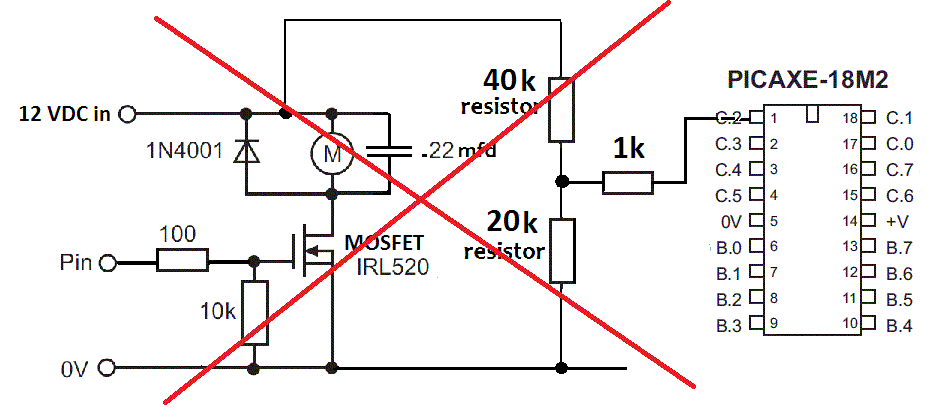
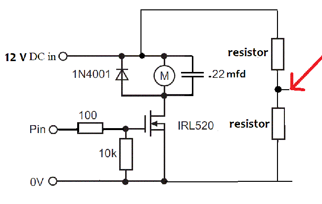
I have been reading over some of the posts regarding back EMF, but much of it is over my head. So far I hope I figured correctly that the first step is to take a reading at the red arrow in my diagram below. I need help figuring the values of the 2 resistors that I assume create a voltage divider. What come up with is 10k for each. I just want to do a crude cruise control based on a medium speed corresponding to this line of my code "pwmout B.6, 99, 325" with the frequency at 8mh. So I need to measure the reading at the arrow under normal load on level track, then on an incline? So when the reading goes below (or above?) a certain figure, I will change the pwmout to a higher preset speed.


So with a READADC from the red arrow, I should get a usable number?

Thanks,

Take care, Joe.
 
Last edited:

rq3

Senior Member
Joe, take a step back and look at the big picture (nice schematic, by the way!). If the motor is not running at all (i.e., the MOSFET is OFF), what's the voltage at your red arrow? 6 volts, right? Ouch!

With a bit more info on the motor and the current you're expecting it to use, you could think about introducing a current sense resistor after the MOSFET source, and triggering your "gear shift" from the voltage drop across that. We need more details!

Rip
 

AllyCat

Senior Member
Hi Joe,

As far as I can see, all you will ever measure at the red arrow is 6 volts (i.e. 12 volts * 10k / 20k ).

A motor is a complex device: it has resistance, inductance and can be a voltage source (the back emf). Basically, most motors and generators are the same - when a motor is rotating it generates a voltage which is in a direction to reduce the current flow. Hence the large "inrush" current (if the full supply voltage is applied) until the motor starts rotating quickly (i.e. I = Vsupply / R , until the -Vbackemf builds up).

The problem is separating the back emf from other voltage drops in the circuit (Vsupply and I*R). Is the IRL520 a PWM driver? If so, then you might read the back emf during the "off" part of the cycle, but there are (at least) two problems: Firstly you'd need to sychronise the ADC reading with the PWM cycles. Secondly, during the "off" part of the cycle, current is flowing in the "flywheel" diode (1N4001) with about 0.7 volts across the diode. So the back emf is "buried" somewhere within the motor.

IMHO it would be far better to add a physical "tachometer" sensor onto the motor shaft, maybe magnetic (reed, Hall effect or a "generator" coil), optical, or even a simple physical switch (eccentric cam or commutator, etc.) and detect the pulses or analogue voltage with the PICaxe.

Cheers, Alan.
 

joe paul

Senior Member
Joe, take a step back and look at the big picture (nice schematic, by the way!). If the motor is not running at all (i.e., the MOSFET is OFF), what's the voltage at your red arrow? 6 volts, right? Ouch!

Rip
Hi Rip,

Thanks for the info! Wishful thinking on my part that there was a simple solution. Actually the supply voltage is closer to 14 volts, but I was thinking I could adjust the resistors to 2 different values to give me something acceptable, if necessary. Thanks for the heads-up on the over-voltage!

I will keep everyone posted!

Take care, Joe.
 

joe paul

Senior Member
Hi Joe,

IMHO it would be far better to add a physical "tachometer" sensor onto the motor shaft, maybe magnetic (reed, Hall effect or a "generator" coil), optical, or even a simple physical switch (eccentric cam or commutator, etc.) and detect the pulses or analogue voltage with the PICaxe.

Cheers, Alan.
Hi Alan,

Thanks for the info! I was thinking about a trackside controller where, somehow, I could measure the change in current draw from the motor on the power supply, assuming that if the demand went up, the motor was under more of a load, or something like that. I am not an electrical scholar by any means. Could count revolutions of a wheel, but that would mean I have to have something in the loco, not trackside. So perhaps speed sensing based on the time it takes to travel over 2 separate points, sort of like the traffic cops would do years ago to determine if you were speeding. So guess I need to figure how to count the time difference between 2 pulses to crudely determine speed.

Thanks for the detailed explanation!!!

More to ponder!!!!

Take care, Joe.

P.S. The IRL520 is just a MOSFET. J.
 
Last edited:

AllyCat

Senior Member
Hi Joe,

Yes, a curent measurement may give some indication of speed, but note that the current should actually fall as the motor turns faster. However, there are many other (loading) factors which may affect the current, such as the number of wagons, gradient, acceleration, etc.. So a more direct "time of flight" measurement of speed might be more suitable.

If some part of the train has an identifyable "flag" of known dimensions (e.g. the size of a wheel or wagon, a tiny added mirror or magnet, etc.) then only a single sensor is required and PULSIN might give a satisfactory value.

PICaxe doesn't have any direct method to measure the time bewteen two pulses, so you either need additional hardware (e.g. a flip-flop) or you can use a simple software polling loop (Pseudocode: DO : LOOP UNTIL pulse1 : DO : INC counter : LOOP UNTIL pulse2 : speed = distance / counter).

Cheers, Alan.
 

joe paul

Senior Member
Hi Alan,

Thanks for the reply and info! I use magnets and reed switches quite a lot already with relays, so that would work for the PULSIN, I guess, with a couple reeds between the rails (spaced a few inches apart) and a magnet on the underside of the loco. This doesn't have to be very precise, just that it works. Before getting this PWM circuit up and running, I used preset fixed voltage to inclines, declines and level track. Sort of fun to see the train speed up a foot before the grade and take the hill. Perhaps a reed switch just to ramp up the speed a few inches before the grade, and another at the apex (to slow it down) would be enough, with the speed sensing used on the flat areas to set the average speed. Boy, so many options!!!!!!!

Thanks!

Take care, Joe.
 
Last edited:

Pongo

Senior Member
I found a good resource for back-emf RPM measurement here.

You can measure back-emf in a PWM drive, but only during the time that the driving mosfet is OFF. I very much doubt that the picaxe is going to be fast enough to do that.
 

joe paul

Senior Member
Hi Pongo,

Thanks for the info! I saw a diagram like the one in your link:

and that is how I worked up my failed idea.

I will try to wrap my head around it!

Thanks for the link! Learning something new all the time.

Take care, Joe.
 

joe paul

Senior Member
Hi Pongo,

Thanks again for the info! So much of this is way over my head, but I am willing to learn!

Take care, Joe.
 

edmunds

Senior Member
Well. Would you actually have to dismantle the pwm to get to the low part of the cycle? I think you could just switch it off and measure. If you can do this and switch the pwm back on inside, say 20ms for a model train locomotive with flywheel on the motor, this should be doable. Not complete code, but just an idea:


main:
hpwm 0, 0, %0001, 110, 150 'forward
pause 2000 'whatever it takes for the motor to get up to the intended running speed
hpwm OFF 'disconnect the pwm
pause 2 'in case you are measuring too soon
readadc10 1, w27 'read back-emf value
sertxd ("Back-EMF is: ",w27) 'display back-emf value or do something else with it

goto main

I might have time later today to actually try this.

Edmunds
 

edmunds

Senior Member
Works like a charm :)

Well, this actually works :).

I get load-free values between 400 and 600 and loaded values grow significantly up to 1023 at stall. Now it is just a question of interpreting the numbers and doing something with them.


Cheers,

Edmunds


Code:
#picaxe20x2

#no_data
#no_table

setfreq m16


main:
 hpwm 0, 0, %0001, 100, 199                  'forward
 pause 100
 hpwm off
 readadc10 1, w0
 sertxd (#w0,10,13)
goto main
 
Last edited:

AllyCat

Senior Member
Hi,

I found a good resource for back-emf RPM measurement here.
Yes, that's an excellent App Note, covereing most of the theoretical and practical aspects. But I wouldn't want to develop such a system without a 'scope! ;)

Do note that their example motor is a very small, low voltage, high speed device, being operated at a low PWM frequency and duty cycle. The "sawtooth" (current) mode of operation means that the peak current will be much higher than the average; at least 3 - 4 times and in their example perhaps nearer 20 times. But this mode of operation does have benefits for low speed models because the individual "kicks" of current can overcome static friction and give a subjectively "high torque", low speed drive.

Also note that the current is being measured relative to the positive supply rail (hence the value of 1023 when there is no back-emf) and that the inductive voltage "spike" after the FET switches off needs to be "ignored" (gated) in some way. But within these constraints, and for PWM operation below about 100 Hz, a PICaxe may well be able to work well.

However, I'd still recommend a more direct Keep It SimpleS approach: If you want to measure speed (= distance / time), then measure distance and time and not some complex value (in terms of theory and maths) which may be further "clouded" by effects such as motor loading and temperature, etc..

Cheers, Alan.
 

joe paul

Senior Member
Hi Edmunds,

Many thanks for taking the time to work all of this out!

There isn't a flywheel on the motor, but a 1/10th of a second pause shouldn't matter, especially if the motor starts right back up, which I assume it will. Probably wouldn't even notice it.

Where am I measuring this value and how would I prevent the over-voltage if the motor power supply to the motor is delivering 12-14 VDC? Is it just a matter of tapping into a voltage divider (with resistors of varying values) where I wouldn't get more than 5 VDC max?

Thanks!

Take care, Joe.
 

joe paul

Senior Member
However, I'd still recommend a more direct Keep It SimpleS approach: If you want to measure speed (= distance / time), then measure distance and time and not some complex value (in terms of theory and maths) which may be further "clouded" by effects such as motor loading and temperature, etc..

Cheers, Alan.
Hi Alan,

Thanks!

I willing to try everything. But the result doesn't need to be precise or perfect, just a little better than nothing at all. It is a learning experience for me and I thank everyone for their kind help!

Take care, Joe.
 

joe paul

Senior Member
Hi Folks,

I guess I should explain myself a little better. I am working on the PWM control for several different situations with the Bluetooth. One, which I show in my last vid, is the "on-board" version similar to the commercial boards installed in a loco. The other is for trackside control or a trackside throttle with no boards in the loco. The there would also be a small automated display where turnouts and animated things would be run, with music and sound effects, automatic or by remote. Next I would like to learn to use the little servos. I currently do mechanical animated animals with mechanisms built on continuous rotation into reciprocal motion. So servos later on for a simpler mechanism and a random effect is fantastic . A whole new world for me! But I am rusty with BASIC, and the Picaxe BASIC is a little different from the BASIC Plus I learned back in 1977 and the Timex/Sinclair BASIC I learned on my own back in the late 1980s (I got into the T/S 1000 a little late in the game). And I have no formal training or schooling in electronics, so I fly by the seat of my pants many times, and build on what I know at the time. Thank God for beginner's luck!!!!

So, all ideas and solutions work their way in these projects. I really like the Picaxe system, just wish all the attention on the net wasn't for the *rdu*n* line, with their "shields" and "sketches."

Thanks, everyone, for all the suggestions, tips, code examples, corrections, and advice!!!!!!!!!

Take care, Joe.
 

eggdweather

Senior Member
I've been study the application note here: http://www.precisionmicrodrives.com/application-notes-technical-guides/application-bulletins/ab-021-measuring-rpm-from-back-emf and the Arduino code and Edmunds code above and conclude Edmunds code is a working and very practical solution, although you should consider adding a small series resistor say 1K to protect the PICAXE a input, and as a relative speed measurement with linearity issues corrected for in software makes an excellent project and solution to my mind.
 

joe paul

Senior Member
Hi Eggdweather,

Thanks for the info!

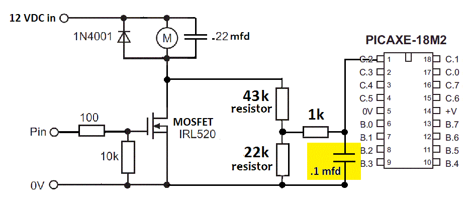
So is this the circuit with a voltage divider that shouldn't yield more than 5 VDC on 12-14 VDC, with the 1k resistor on the ADC input?


Thanks for the help!

Take care, Joe.
 

eggdweather

Senior Member
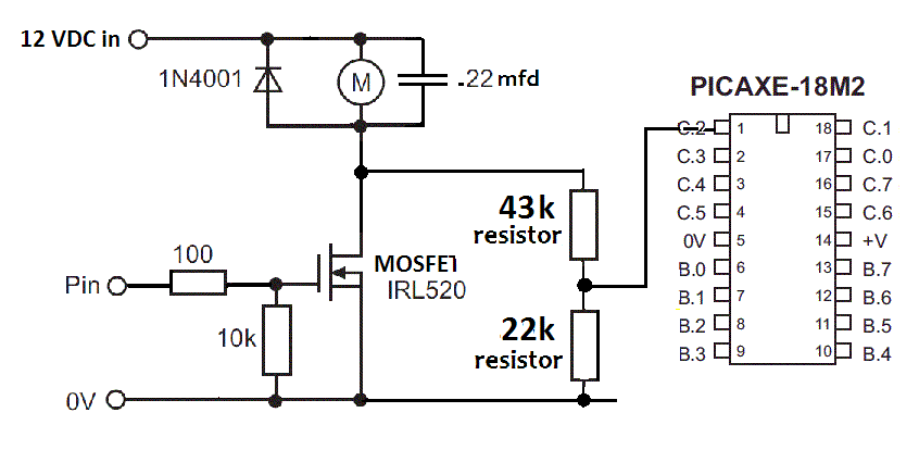
Yes, but move the top end of the 40K to the top of the MOSFET, then your diagram is correct and the software from Edmunds above will read your B-EMF. the 40 and 20K R will need to be nearest preferred values, 43K and 22K giving the following detection voltage range:
14v input = 14 x 22/(22+43) = 4.73volts
12v input = 12 x 22/(22+43) = 4.06volts
 

joe paul

Senior Member
Hi Eggdweather,

So is this it? I saw a small cap added in one diagram, so I temporarily added here, highlighted in yellow. Does it matter?


Thanks!

Take care, Joe
 

eggdweather

Senior Member
Yes, that capacitor will help to smooth out voltage fluctuations at the picaxe input, it's time-constant is (T==R.C) 4.4mS to charge and about 2.2mS to discharge so you may need to take account of that in your reading frequency, for example the PWM will need to off for 4.4mS before you start reading the B-EMF and (highly simplified value) when the PWM is on, the C will charge to the average PWM voltage divided by ~2, thereby giving you a false reading. So get around all that by waiting a short while before you read, say PAUSE 5 then read but don't come back too quickly (like in 5mS) to do all that again, perhaps once a second.
 

AllyCat

Senior Member
Hi Joe,

Yes, connect the 40k to the anode of the diode, not to the cathode. The 1k is not necessary because Thevenin tells us that the impedance at the divider junction is already about 13k. Strictly (according to the Microchip data sheet) it should be less than 10k, so I'd use 30k + 15k, or lower. Or put a small capacitor (perhaps 1nF) between the PICaxe ADC input pin and ground.

You might calibrate the zero-emf value by taking an ADC reading when the FET is off and the motor not rotating. But if your 12v rail is not "rock solid" (regulated), then I'd use another divider (perhaps 1k8 + 1k0) from the supply rail (i.e. as shown in your earlier diagram) to the "External Reference" input of the PICaxe ADC.

Cheers, Alan.
 
Last edited:

joe paul

Senior Member
Hi Eggdweather,

Is that cap highlighted in yellow really necessary if it would then require that I turn off the PWM for a longer period? I don't need the best numbers; I would only look for a certain value to indicated a load within a range greater than a figure. I wouldn't be working with the number to calculate the duty cycle or anything, just to bump up the speed a little, how I am thinking so far.

Thanks!

Take care, Joe.
 

joe paul

Senior Member
Hi Alan,

So you are telling me, if I understand correctly, that the cap I added highlighted in yellow would be good to keep but not use the 1k resistor to the ADC input? Or can it stand as drawn? Forgive me if I seem confused.

Thanks!

Take care, Joe.
 

AllyCat

Senior Member
Hi Joe,

Yes, the present diagram could stand, but the 1k is doing nothing useful.

IMHO 100nF (0.1uF) is rather too large, it might take more than 5ms for the voltage to stabilise adequately.

Cheers, Alan.
 

edmunds

Senior Member
Hi Eggdweather,

So is this it? I saw a small cap added in one diagram, so I temporarily added here, highlighted in yellow. Does it matter?


Thanks!

Take care, Joe
Joe,

This is the circuit I used with the exception of voltage divider, since my power source is a single LiPo cell - 4.2V tops. I tried 10k resistor between the motor and picaxe and if I remember correctly it did work, but I suspected it can be part of problems and switched to 1k now. I did not add the capacitor, but I will, sure, need to experiment with that. I also discovered I had to make both outputs of my motor controller (I'm using MPC15C724) high impedance before I got any meaningful results. This is still far from good and complete, behaves strangely sometimes and has lost the remote control speed function. Just did not have time to think all of it through (or brains) :). The model car this is sitting in, however, is now helping with extra power to the motor to push upwards and applies brakes when going downhill. Looks really cool! Now, further improvement will be difficult without connecting all of this to my PCBScope and this will take me a day or two, since I need to replicate the setup in some way I can actually connect to it in the right places. With a PCB of 17x13mm it is a little tricky ;).

This is my code, take what you can use:

Code:
#picaxe40X2

setfreq m16                     

'Outputs for lights
Symbol BLKL = B.6               'Blinker Left
Symbol BLKR = A.2              'Blinker Right
Symbol BRKL = D.6              'Brake Lights
Symbol HL = D.4                  'Headlights
Symbol RUNL = C.7              'Running Lights
Symbol FOGL = D.7              'Fog Lights
Symbol REVL = C.6               'Reverse Light

Symbol BLUE1 = D.2             'Blue Light 1
Symbol BLUE2 = D.1             'Blue Light 2
Symbol BLUE3 = D.0             'Blue Light 3
Symbol BLUE4 = C.3             'Blue Light 4

Symbol AMBL1 = C.5            'Ambient Light 1
Symbol AMBL2 = C.4            'Ambient Light 2
Symbol AMBL3 = D.3            'Ambient Light 3

'Outputs for main motor
Symbol Motor1 = D.5           'Motor connection 1
Symbol Motor2 = C.2           'Motor connection 2
Symbol PSave = B.7              'MPC17C724 on/off signal

'Outputs for servos
Symbol Servo1 = B.3            'Servo 1
Symbol Servo2 = B.4            'Servo 2
Symbol Servo3 = B.5            'Servo 3

'Transistor buffered outputs for AUX loads up to 100mA each
Symbol AUX1 = C.1              'AUX1 exit (buffered up to 100mA)
Symbol AUX2 = C.0              'AUX2 exit (buffered up to 100mA)

'IR receiver inputs
Symbol IRSENS1 = B.1            'IR receiver 1 in front of the car
Symbol IRSENS1Pin = pinB.1
Symbol IRSENS2 = B.2            'IR receiver 2
Symbol IRSENS2Pin = pinB.2

'IR outputs
Symbol IRLEDL = A.3            'IRLED in the back of the vehicle - left hand side
Symbol IRLEDR = A.6            'IRLED in the back of the vehicle - right hand side
Symbol IRLEDID = A.5           'IRLED for signaling ID of the vehicle - underbody

'For serial connections to additional devices
Symbol DATApin = A.0
Symbol CLKpin = A.1

'Not assigned and not connected
Symbol A7pin = A.7
Symbol B0pin = B.0

'Byte variables
Symbol Hundreds = b1
Symbol Tenths = b2
Symbol Units = b3
Symbol ID = b4                     'Vehicle ID
Symbol IRCode = b6             'IR code received
Symbol LoopCounter = b7    'Main Loop counter
Symbol Speed = b8               'Current speed value
Symbol NewSpeedBEMF = b16
Symbol NewSpeed = b9        'New speed value
Symbol BLKCounter = b14    'Counter for blinkers
Symbol BRKLCounter = b15   'Counter for brake lights
Symbol IDCounter = b16
Symbol Counter = b17           'just a counter

'Flag variables
Symbol BLKLONFlag = b10
Symbol BLKRONFlag = b11
Symbol BRKLONFlag = b12
Symbol OvertakingAllowedModeFlag = b13
Symbol DistanceVal = b14

'Word variables
Symbol LiPoVolts = w27        'Battery voltage storage value
Symbol BackEMF = w26         'Main motor back-EMF value
Symbol BackEMFAgr = w25    'Agregated BackEMF for average value calculation
Symbol SpeedBEMF = w24
Symbol MinSpeedBEMF = w23
Symbol MaxSpeedBEMF = w22

'Constants
Symbol BatteryLowTresholdTenths = 3        'Set up "Battery Low" voltage here
Symbol BatteryLowTresholdUnits = 8
Symbol SlowDn = 20
Symbol BEMFFactor = 15

init:
'  gosub LoadEEPROM

  low BLKL
  low BLKR
  low BRKL
  low RUNL
  low HL
  low BLUE1
  low REVL
  low Motor1
  low Motor2
  low PSave                            'to switch the MPC17C724 on
  low AUX1
  low AUX2
  
  BLKLONFlag = 0
  BLKRONFlag = 0
  BRKLONFlag = 0
  OvertakingAllowedModeFlag = 0
  LoopCounter = 0
  BLKCounter = 0
  BRKLCounter = 0
  Speed = 150                           'practical MIN= 55(~14%); MAX=190(~48%)
                                                 'theoretical 25% = 100; 100% = 400
  NewSpeed = 150
  SpeedBEMF = 150
  
'Show the decoder is on
  high BLKL : high BLKR
  pause 1000
  low BLKL : low BLKR
  pause 1000
  high BLKL : high BLKR
  pause 1000
  low BLKL : low BLKR
     
main:
  inc LoopCounter
'Set up PWM for the main motor
  hpwm 0, 0, %0001, 100, Speed                  'forward
'  hpwm 0, 0, %0010, 100, Speed                  'backward

'IR receiver is idling high, so on incoming signal, the pin goes low
  if IRSENS1Pin = 0 then
    irin IRSENS1, IRCode
    select case IRCode
;    case 9 to 40 :        NewSpeed = IRCode

;    START OF CODE FOR DEBUGING SPEED CONTROL WITH PICAXE/SONY REMOTE

    case 11 : if NewSpeed < 190 then : inc NewSpeed : endif
    case 98 : if NewSpeed > 55 then : dec NewSpeed : endif

;    END OF CODE FOR DEBUGING SPEED CONTROL WITH PICAXE/SONY REMOTE

    case 41 :               gosub SetUpID
    case 61 :               NewSpeed = 1
    case 62, 0 :               BLKLONFlag = 1
    case 63, 1 :               BLKRONFlag = 1
    case 64, 2 :               BLKLONFlag = 1 : BLKRONFlag = 1
    case 65, 3 :               gosub BlinkersOFF
    case 66, 4 :               high RUNL
    case 67, 5 :               low RUNL
    case 68, 6 :               high HL
    case 69, 7 :               low HL
    case 97 :               OvertakingAllowedModeFlag = 1
    case 98 :               OvertakingAllowedModeFlag = 0
    endselect
  endif
  
're-write to case statements?  
'decrease speed if lower speed command was received
  if Speed > NewSpeed then           'deaccelerate, break
    dec Speed
    hpwmduty Speed
    BRKLONFlag = 1                         'to start brake light
    BRKLCounter = 0                          'to restart the brake light in case more than one step down
    pause SlowDn
  endif
'increase speed if higher speed command was received
  if Speed < NewSpeed then           'accelerate
  	inc Speed
    hpwmduty Speed
    low BRKL
    BRKLONFlag = 0
  	pause SlowDn
  endif
  
  if Speed = NewSpeed then
  	SpeedBEMF = Speed  * 1024 / 4 / 100 + 400
    MinSpeedBEMF = SpeedBEMF - BEMFFactor
    MaxSpeedBEMF = SpeedBEMF + BEMFFactor
  
    Select case BackEMF
    case <= MinSpeedBEMF
  	NewSpeed = NewSpeed + 10
    case >= MaxSpeedBEMF
  	NewSpeed = NewSpeed - 10
    endselect
  
    debug Speed
  endif

'Brake light ON for 5 loops  
  if BRKLONFlag = 1 then
  	select case BRKLCounter
  	case <= 4                                      
    	high BRKL
    	inc BRKLCounter
  	case 5
  		low BRKL
  		BRKLCounter = 0
  		BRKLONFlag = 0
  	endselect
   endif
  
'left blinker ON phase for 5 loops
  if BLKLONFlag = 1 and BLKRONFlag = 0 then
  	select case BLKCounter
  	case <= 4                                      
    	high BLKL
    	inc BLKCounter
  	case 5 to 9                                 'switch over to OFF phase for 5 loops
  		low BLKL
  		inc BLKCounter
  	case 10
  		BLKCounter = 0
  	endselect
   endif
   
'right blinker ON phase for 10 loops
  if BLKLONFlag = 0 and BLKRONFlag = 1 then
  	select case BLKCounter
  	case <= 4 
    	high BLKR
    	inc BLKCounter
  	case 5 to 9                                  'switch over to OFF phase for 10 loops
  		low BLKR
  		inc BLKCounter
  	case 10
  		BLKCounter = 0
  	endselect
  endif

'hazzard lights ON phase for 10 loops
  if BLKLONFlag = 1 and BLKRONFlag = 1 then
  	select case BLKCounter
  	case <= 4 
  		high BLKL
    	high BLKR
    	inc BLKCounter
  	case 5 to 9                                 'switch over to OFF phase for 10 loops
  		low BLKL
  		low BLKR
  		inc BLKCounter
  	case 10
  		BLKCounter = 0
  	endselect
  endif
    
  irout IRLEDID, 1, ID
  irout IRLEDL, 1, Speed

  if OvertakingAllowedModeFlag = 0 then                      'if overtaking is not allowed, operate rear right hand side IR LED as well
    irout IRLEDR, 1, Speed
  endif
  
'Things to do every 10th loop
  if LoopCounter = 10 then

'LiPo test
  calibadc10 LiPoVolts
  LiPoVolts = 10486/LiPoVolts
  bintoascii LiPoVolts,Hundreds,Tenths,Units
  Sertxd (Tenths,".",Units,10,13)
  if Units = 8 then
  	gosub BatteryLow
  endif
  
'Reset counter  
  LoopCounter = 0
  
'Back-EMF code (has to remain the last thing of the loop)
  hpwm OFF                               'switch off the motor
  high PSave                               'MPC17C724 outputs to high impedance
  pause 4
  readadc10 12, BackEMF           'input ADC12, B.0 for now
  sertxd (#BackEMF,10,13)
  low PSave
  endif
goto main

BlinkersOFF:
  low BLKL
  low BLKR
  BLKLONFlag = 0
  BLKRONFlag = 0
  BLKCounter = 0
return

BatteryLow:
return

SetUpID:
  write 0, IRCode
  for IDCounter = 1 to IRCode        'recognize the new ID by blinking it with hazzard lights
    high BLKL : high BLKR
    pause 2000
    low BLKL : low BLKR
  	pause 2000
  next IDCounter
return

LoadEEPROM:
  read 0, ID
  if ID = 0 then
    write 0, 1
    read 0, ID
  endif
return
 

joe paul

Senior Member
Hi Folks,

How wonderful this is that I can get this level of expertise from all over the globe!!!!

Many thanks, everyone!!!!!!!!!!!!!!!!!!!!!!!!!!!

So, I take it that this diagram below a good working start for me, understanding that I still need to tweak it:


Take care, Joe.
 

joe paul

Senior Member
Hi Alan,

Thanks for all the info and suggestions! Now I need to get out the soldering iron!

Take care, Joe.
 

joe paul

Senior Member
Hi Edmunds,

Thanks for the info and code. I will have to really apply myself to your code and play around with it. I am sure there are many things in there I may eventually use. I learn from examples more than theory, so it comes in handy!

Take care, Joe
 

Pongo

Senior Member
Well. Would you actually have to dismantle the pwm to get to the low part of the cycle? I think you could just switch it off and measure. If you can do this and switch the pwm back on inside, say 20ms for a model train locomotive with flywheel on the motor, this should be doable.

Edmunds
Nice enhancement of the concept :D
 

edmunds

Senior Member
Hi Edmunds,

Thanks for the info and code. I will have to really apply myself to your code and play around with it. I am sure there are many things in there I may eventually use. I learn from examples more than theory, so it come in handy!

Take care, Joe
Please, take this as a work in progress thing where some things do not work... :). I hope to improve and clean it up during holidays.


Cheers,

Edmunds
 

BeanieBots

Moderator
This is getting far more complex than it needs to be!
Back emf is the voltage generated by the speed of the motor.
If the motor was 100% perfect, the back emf would exactly equal the voltage across it.
More to the point, it would stay at that speed regardless of load, taking infinite amps for an infinite load.
Unfortunatley, motors are not 100% perfect, but we can make them look like they are!

The imperfection is mainly due to armature resistance.
The voltage dropped by this resistance is the difference between the voltage across the motor and the back emf.
You can measure the resistance with a DVM.
You can measure the current.
So, you know the voltage dropped by the resistance for a given current.
Therefore, you can work out the back emf by measuring the current.

If you put a resistor in series with the motor that is same resistance as the armature, then measure the voltage across the resistor and add that voltage to the supply to the motor, you will have compensated for the loss and made the motor look perfect.

This is a well known technique call "IR compensation".

In real life, it is not very efficient to match the resistance and a much lower resistance plus amplification is used.
If your motor is only an amp or so, you can use a resistor of about an ohm or maybe a bit less and feed it straight into a PICAXE ADC pin.
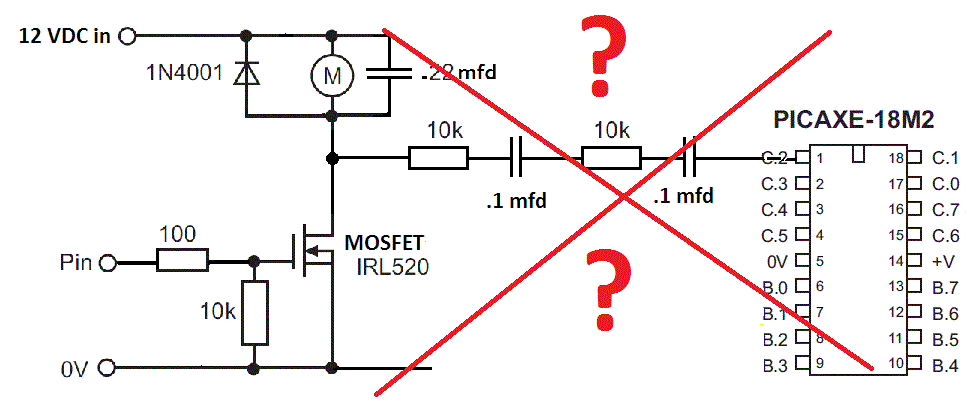
If you are using PWM, average it out with 10k feeding 100nF and then another 10k feeding another 100nF before the ADC.
Then simply add the ADC value to the PWM value and you have a very simple compensated speed control.
You can play changing the gain (multiply or divide the ADC value) before it is added.
Any over compensation will become unstable, under compensated will give a sloppy control.

Have fun, and good luck with your project.
 

joe paul

Senior Member
Hi Edmunds,

Thanks for the link. I guess I have to learn Arduino C at some point, but I think that ship has sailed!

Take care, Joe
 

Circuit

Senior Member
There is another approach to maintaining the speed/torque of a model railway motor; just use a variable voltage regulator such as an LM317. A voltage regulator tries to maintain the voltage as the load varies; therefore it acts very much like a back-emf control on a motor. Clearly it is not true back e.m.f. control, but the effect is much the same. Just hook up an LM317 set up as a variable voltage supply and you will see your model locomotive maintain the same speed whether up a gradient, on the flat or down a gradient. Plenty of simple circuit diagrams in the datasheets from the various manufacturers of the LM317. It really works well in practice. Furthermore, many modern model railway locomotives, especially in the smaller gauges, have coreless motors and the directions-for-use often advise against using P.W.M. controllers.
 

joe paul

Senior Member
Hi Circuit,

Thanks for the info!

I can use PWM with the motors I have. I found the PWM works with my older open frame AC/DC universal motors, also. So far the Bluetooth throttle built with the Picaxe works very good, IMO. I want to be able to vary the speed then hold it constant at whatever speed I want, and also do gradual stops and starts.

Take care, Joe.
 

edmunds

Senior Member
If you are using PWM, average it out with 10k feeding 100nF and then another 10k feeding another 100nF before the ADC.
Then simply add the ADC value to the PWM value and you have a very simple compensated speed control.
You can play changing the gain (multiply or divide the ADC value) before it is added.
Any over compensation will become unstable, under compensated will give a sloppy control.

Have fun, and good luck with your project.
How would 10k+100nF x 2 average it out? I was thinking I should do some software based averaging, but that takes measuring and calculation time, which is a bottleneck here.

ADC value is a number. What do you mean with PWM value? Frequency? Period? Duty? An equation of the three? My practical numbers are, say, 570 for ADC (changing in the range of +/-50), 110 for pwm period and, say, 150 for pwm duty.

You seem to know a lot more about the physics of DC motors than I do, so I'm not questioning your suggestion, but willing to understand it to be able to apply it.


Thank you for your time,

Edmunds
 
Top