How tough is a Picaxe chip ?

donrecardo

Senior Member
Q. How tough is a Picaxe chip ?

A. Tougher than I would have believed

I wanted to build a circuit that required a Pic16F1827 and I don't have one ,
but I remembered reading that the 18M2 is based on that or a similar chip.

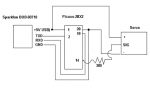
The circuit was to measure and the voltage on a car battery and display it
on a 4 digit common cathode display . (http://embedded-lab.com/blog/?p=3096 )


As I had 2 18M2 chips I figured I would lose the built in program and use it as a
straight 16F1827 . I built the circuit and programmed the chip and it sort of worked .
It showed a reading on the display but the reading wasn't telling the truth.
I was sat thinking what might be wrong for a couple of minutes or more when I happened
to touch the Picaxe chip and it burned off my fingerprint from the tip of my finger.
I switched off and had a poke around ( after it had cooled down)
The circuit takes an input voltage of up to 16.9V and feeds an ADC input via a voltage
divider . I also use this input to feed a 5v regulator to run the picaxe chip.
Sadly I had connected the picaxe to the input rather than the output of the regulator
so I was powering the the picaxe with 13.8v ( for more than 2 minutes )

I corrected my mistake . took out the fried chip and replaced it with a new one which I
had programmed . with the chip powered with 5v now as it should be it worked fine .

Just out of interest , I swapped the chip back to the one that was well fried and , you guessed it.
It works just fine . It had taken an over voltage of 13.8v for more than 2 minutes and it still works

Thats what I call a tough chip

Don
 

nick12ab

Senior Member
I dont know
This is what the M2 parts datasheet says
The M2 parts have an internal 3.3V silicon die, but also contain an internal Low Drop Out Regulator, which is automatically enabled when required. This means all M2 parts can be used across the entire 1.8 to 5V voltage range.
Hippy or Technical may come back with a more detailed answer.
 

Dippy

Moderator
I think you were very, very lucky Don. Next time.....?


I don't know the answer re: M2 , but the PIC data sheet implies the LDO is for the internal reference and it still gives a MAX Vdd (+v voltage supply) rating of 5.5V - though my old data sheet is marked "preliminary".

Jamster, get yourself an anti-static mat and strap etc. :D
I won't let you anywhere near my Infineon Tricores!
 

fernando_g

Senior Member
Now, only take it with you while scuba diving to 100 ft. :rolleyes:

Seriously, I've also sometimes overstressed som Picaxe chips like you did (although not as high a voltage).
I've found then that they remain operational. Or at least they appear so, but one never knows if, for instance, one of the RAM locations has become unoperative.
However I still do not throw them away...... I put a permanent red dot or something, to remind me that these should only be used in non-critical apps.
 

nick12ab

Senior Member
Seriously, I've also sometimes overstressed som Picaxe chips like you did (although not as high a voltage).
I've found then that they remain operational. Or at least they appear so, but one never knows if, for instance, one of the RAM locations has become unoperative.
However I still do not throw them away...... I put a permanent red dot or something, to remind me that these should only be used in non-critical apps.
I've never had an overstressed PICAXE remain fully operational and they've either completely died or most of it survives and only one or two things die: no external resonator or crystal can be used, or a pin dies, or it runs abnormally hot or the state of one outpin affects the state of another, or it runs at about 2/3 of normal speed when operating from the external resonator (yes, really!). Those get stickers put on the bottom of them to remind me what's wrong with each one.
 

NXTreme

Senior Member
I also have noticed how durable the Pic chips are. I recently plugged the power supply for a 20X2 in backwards. Fortunately, it was current limited to 180 mA, but even then, I didn't notice 'till about half an hour later when I tried downloading a program and it wouldn't program. It still works just fine :).

I idiot-tested a DS18B20 last month. I got the power leads mixed up (again!) and this time there wasn't any current limiter...! This time it only took about three minutes to notice that the program wasn't returning values that made sense. Anyways, I quickly clued in and yanked it out, only to get two little spots burnt into my fingers. I'm sure it was close to the thermal design limit of 125C! :D
 

Dippy

Moderator
Seriously though, there is a difference between the chip body surface temperature caused by ambient heat and internal heat.
If that surface heat was caused internally just think how hot the semi got.

It's difficult to trust something if it's had a hard time. Though marking it and keeping it for later testing (or non-important jobs) sounds like a good idea.

Just make one promise; when you use an abused PICAXE in a project and it plays up then please try another PICAXE before posting your woes on the Forum :)
It might take days before there is a confession...
 

NXTreme

Senior Member
Yes, I do know that once you use a Pic (or Picaxe) out of spec, there is no guaranteeing what will happen. I only use "battered" pieces of semi for tinkering, nothing important.

I promise on my hot soldering iron that I shall not create problems with/about mis-treated chips :).
 

Dippy

Moderator
Curry, the magnet query cropped up a while ago. I'm surprided Ec didn't search for you.:confused:

After considerable waving of magnets and research on various sites / App Notes it was concluded that there was no effect when using 'typically available' strong magnets.
How it might behave with a monster or inside an MRI scanner is another story... we'll have to ask Mr Hall.

So, don't worry.
 

Xarren

Member
Then again, when it comes to heat, chances are it gets much hotter than that (Although for shorter periods of time) during hot air soldering. I doubt the heat itself is such a big problem.

And magnets shouldn't affect it - You'd need a changing magnetic field to induce a voltage and damage a chip.

Oh, and I have never had a picaxe survive being plugged in the wrong way around or to an incorrect voltage. Never. Do the SMD versions skimp on clamping or anything like that to save space?
 

hippy

Ex-Staff (retired)
Oh, and I have never had a picaxe survive being plugged in the wrong way around or to an incorrect voltage. Never. Do the SMD versions skimp on clamping or anything like that to save space?
PICAXE / PICmicro can survive being plugged in the wrong way round as that's not always a power-rail swap, you often end up parasitically powering it through the I/O pins but not cause damage. It really depends on luck and what's previously been programmed; unlucky enough to pull an output receiving +V power to 0V and similar and that's a lot of current through the I/O pin.

The length of time and nature of the fault may have an affect. Sometimes one gets lucky other times not. The safest course is to power from a current limited supply and hope that prevents any damage before you hit power off.

AFAIK SMD devices are no different to DIP except in size.
 

Dippy

Moderator
Well done Westy, you must be bored today? :D
You're taking Ec's job away from him.


Of course heat is a problem Xaren. Ultimately heat/temperature kills.
Yes, hot-air / reflow will get bloomin hot , check out Microchip AN233 if you want their notes.

But you don't seem to understand; IF the heat is generated by internal currents then the chip surface temperature will be far lower than the semiconductor junction that is producing that heat. If the case is Q-Hot the semi will be F-hot.

Applying an external heat for reflow is a ramped and even process for a controlled time, whereas a red-hot semi junction may be a tiny point source at a destructive temperature. Worse still, a partially destructive temperature.
There will obviously be temperatures at which things burn, melt, fracture or your doping falls out.

I'm blooimg amazed these chips can take as much wellie as they do.

And i thorouglhy agree with hippy about current limited supplies. In fact I bang on about them quite a lot.
Anyway, carry on frying and I'll phone my Broker.
 

srnet

Senior Member
One thing I would recommend is that when you accidently connect your Microprocessor board to the mains, make sure you are wearing a pair of those welding goggles.
 

Goeytex

Senior Member
Accidents happen.

Once I powered an 18M2 with 11.8v off an on for an hour or so when prototyping a Picaxe to NRL2401+ RF module setup. Couldn't figure out why
the Module was not receiving. SPI signal looked good. Finally sorted it out when I checked voltgae to the Noridc module. Fried the Nordic
module receiver section, but the Picaxe survived with seemingly no ill effects. But I wouldn't use it in a pacemaker now. :p

Was not so lucky with a 20x1 with something similar. Fried immediately.
 

nick12ab

Senior Member
...the Picaxe survived with seemingly no ill effects...Was not so lucky with a 20x1 with something similar. Fried immediately.
Again, the 18M2 has an internal regulator but the 28X1 hasn't. The 18M2 is probably rated to only 5.5v as the voltage detection circuits that automatically turn on/off the LDO regulator probably can only work at 5.5v so will be blown at more and either the regulator turns off and you blow up the chip or the regulator stays permanently activated and the lowest operating voltage is increased.
 

nick12ab

Senior Member
the state of one outpin affects the state of another
OK, this is not true (yet) - it was a dead input driver and the infamous read-modify-write issue in a procedure for adding the decimal point onto a 7-segent display. Fixed with 'outpins' variable.
 

Dippy

Moderator
If it's of any interest ... and I prefix the following with "apparently".

THE LDO goes just before the main die but not to the output drivers and something else which I've forgotten..
The PIC is rated to 6.5V Abs max and has not been tested beyond by Microchip.
Beyond this voltage you will probably damage the chip.
I'd make 5.5V your abs max working voltage to be safe.
(This excludes 3V PIC s of course).
 

axe_hackin

New Member
20X2's died

I was testing a 20X2 with an RC servo (no idea what the load is). I did not use a current limiting resistor. Burned up the 20X2. At least I assume I did, because it will not program anymore. I then tried another one, this time with a 380ohm resistor. Worked for a while, now it will not program either.

Does this sound reasonable?
 

Goeytex

Senior Member
Yes, that sounds reasonable.

What kind of noise protection did you use ? What power supply ? What servo ?

Without seeing your actual schematic we can only guess as to why the second one fried.
 

srnet

Senior Member
I accidently connected a 3S Lipo battery (11.4v) to a 28X2 circuit designed for 1S lipo (4.2V).

The series diode was fried, as was the 3V LDO regulator (crater damage), the RFM42 RF module was toast also, plus a LED.

The 28X2 was however undamadged, although its now been demoted to bench testing duties only.
 

westaust55

Moderator
@axe_hackin,
Welcone to the PICAXE forum.

As well as indicating your schematic details it may be useful to post the program.
Do you have any extended pauses, serin commands without timeout, etc.

Have you tried a hard reset as described in PICAXE manual 1.
Either hold the PICAXE in reset or power off then start a download with the PE.
When the pop up window for the download is displayed then release the reset or power up the PICAXE chip.
 

axe_hackin

New Member
20X2.PNG
Code:
#picaxe 20x2
setfreq m8

init: servo [63286], B.4,75 ; initialise servo
main: servopos B.4,75 ; move servo to one end
pause 2000 ; wait 2 seconds
servopos B.4,250 ; move servo to other end
pause 2000 ; wait 2 seconds
goto main ; loop back to start
My 08M is working just fine in the same setup.
 

Goeytex

Senior Member
You are missing the 22K/10K resistors for the download circuit and you have no
decoupling capacitors on either the Picaxe or the servo.

I would suggest that you read Manual 1 and Manual 3 and follow the guidelines for a minimum circuit.

The USB power is limited to a max of 500ma and the FTDI chip has a power byte that is probably limiting
that port to 100ma. Consider that a servo can draw up to 1 amp. I would not recommend running the servo
via the USB power. If you must do this, then I suggest a 220uf bulk capacitor on the USB power line.
 

axe_hackin

New Member
The FT232R board takes care of the buffering and holding the serial line low. I would need those resistors if I was running the chip as a standalone.

I thought about the current requirements. But, Arduino examples show this setup. That is why I tried it. Again, this circuit works FINE with an 08m.

What is different in the 20X2 chip, that it stopped working?
 

Goeytex

Senior Member
You need the resistors. Period. Without them you will have problems.
The fact that you are getting away with not using them on an 8M is irrelevant.
It is a Picaxe not an Arduino. Follow Picaxe recommendations.

You also need the decoupling caps.
 

John West

Senior Member
Also, showing only part of a circuit is not the way to get the best suggestions for solving a problem. Most of the situations where the forum members can't quickly help solve problems are due to the poster leaving out critical circuit or software info.
 

erco

Senior Member
I accidently connected a 3S Lipo battery (11.4v) to a 28X2 circuit designed for 1S lipo (4.2V)...The 28X2 was however undamadged, although its now been demoted to bench testing duties only.
If you made the mistake, why did the 28X2 get demoted? :)
 

srnet

Senior Member
If you made the mistake, why did the 28X2 get demoted? :)
The 28X2 has to judged as suspect, it has had up to 12v across the supply rails. it appears to be OK, but could have a part melted juction or connection ready to fail. So I would not ue it 9built in) to a real application. it was alsoa SMT one, so not easy to replace once buit in.
 

hippy

Ex-Staff (retired)
Back to axe_hackin's expiring 20X2 ( posts #24 and #28 ) ...

It's not always essential to have the 10K/22K download interface resistors between a PICAXE and a USB-to-Serial module but it would be recommended to have a current limiting resistor (1K to 22K ) on the Serial In line and having the download interface in place should not affect things so including it is the easiest option .

Looking at the circuit, except for the USB provided +5V possibly being unsuited for servo operation, there is nothing I can see that should have caused the 20X2's to have expired, and especially as the 08M has continued to function, though that may just be good luck in that it hasn't failed yet.

Because USB cannot supply the current a servo may demand it's hard to analyse why there has been a failure. My suspicions are on a short somewhere but it could be related to the supply issue.

I would suggest testing the circuit on breadboard, using a separate power supply capable of supporting servo current demands, not using the 5V from the USB module at all, and seeing how that works.
 

Goeytex

Senior Member
At this point , I would not assume that the 20x2's have actually expired as no hard reset has been attempted
and no serial test performed.

To prove if the 20x2 are actually blown, I would put them on a breadboard
using the recommended minimum circuit, do a hard reset and then under options
Check Firmware Version. Then attempt to program.
 

axe_hackin

New Member
Hi all,

Good idea about trying it on a breadboard! I just tried it. Still not programming. The transfer to the breadboard performed the hard reset. I even put in the 22K/10k resistors.

I then put the 08M into the breadboard using the same setup -I love the fact that the 08M and 20X2 have the same pinout for +,-,serin and serout.

The 08m performs as expected with and without the servo attached.

I readily admit that I should put more safeties in my circuit.

My point, I guess, is that it seems as though the 08m (12F683) may bemore robust than the 20X2 (18f14k22). Which, I think, is relevant to this thread.

Its too bad I burned out my 20X2's. I was planning on using them to receive MIDI data.
 
Last edited:
Top