How to measure sound with Picaxe?

rmeldo

Senior Member
Hi,

I am thinking of logging the sound level from a microphone.

The idea is to put a specialised chip between the microphone and the Picaxe.

The chip should be able to:

1) interface with the microphone
2) apply a weighting curve (for example A weighting to get the DbA value)
3) send out the measured noise level in a convenient format, i.e. serial, i2c or other for the Picaxe to receive and log.

Do these chips exist?

I need some initial advice to help pointing my internet searches in the right direction.

thanks in advance

Riccardo
 

BeanieBots

Moderator
Trouble with the neighbours?

I'm not aware of any 'chips' that can do that but it's not too hard to do.
All you need is a single satge amplifier to get the microphone signal up to reasonable voltage of around 5v. Then you need a slow decay detector.

The detector is required to convert the high frequency of the audio into a 'near' DC level which can be read by the PICAXE. It can be as simple as a diode into a cap with a high value bleed resistor.

Have a look here for circuit inspiration.
http://www.rev-ed.co.uk/docs/picaxe_sound.pdf
 

BeanieBots

Moderator
If you need a larger dynamic range then it's either a log amp (expensive) or build your own using op-amps and back-to-back diodes in the feedback path to give the log/gain function.

To get the desired frequency range, it is probably best to put a suitable filter between the mic amp and detector stage. The maths for filters such as "butterworth" and/or "sellen/key" is not nice so maybe easiest to use basic "twin-T" type filtering as used by bass/treble controls on HiFi then calibrate against a sound meter.
 
Last edited:

QuIcK

Senior Member
Sounds like your trying to use a picaxe in order to measure noise pollution, as opposed to reacting to it as an input.

correct me if im wrong, but i dont think the picaxes with clock high enough to allow for that frequency range.
human hearing range goes all the way to 20khz, meaning a 40khz sample rate and a brutal filter.

I dont know of any chips that will do this for you. I think a lot of it is done analogue or analogue/dsp on faster chips.

Another downer, im sorry. If you get it into the picaxe suitabley, there is then calibration. that is normally done with a device that you stick the mic into. these cost (i believe) around the £120 mark.
again, this could probably be made diy, but not without cost.

consider that maplin have digital sound level meters for £35. they do a and c weighting, and come factory calibrated.

using one of these sound meters, you could probably hack into it to get what you need. even if you set up something to interpret whats sent to the lcd...
 

rmeldo

Senior Member
Sounds like your trying to use a picaxe in order to measure noise pollution, as opposed to reacting to it as an input
.

Yes that is what I am trying to do.

consider that maplin have digital sound level meters for £35. they do a and c weighting, and come factory calibrated
.

I have one of those meters on my desk. The problem is the usual one. How to ge the 'A' weighted sound level out of the device. I can't open it because it is not mine....at least until I have exhausted other options.

Thanks anyway
R
 

QuIcK

Senior Member
well, i do not know of any chip that you can attach a mic to, and get sound levels out. and i dont think the picaxe is going to be fast enough to apply weighting.
even if the weighting is applied outside of the chip, the picaxe probably wont be able to measure anything above 4khz. let alone process to store.

As you are not trying to recreate the audio, you might be able to get away with something that will turn a full frequency range signal into a dc signal that will represent the maximum value, that can be read with the adc.

anyone know a circuit for this? would the adc be able to do this with little else than an amplifier and eq circuit?
 

BeanieBots

Moderator
@QuIck,
Check the circuit I linked to. That's exactly what it does.
Adding appropriate filtering in the middle is all that's required for weighting.

However, please don't ask me to design the filter:p
(I bet there's a filter designing web page out there somewhere)
 

QuIcK

Senior Member
haha, go me for not reading the whole thread :eek:
well, google is my friend.
a-weighting schematic:
http://sound.westhost.com/project17.htm


I think... *THINK* that that cud be dropped in the circuit BB linked to in between rv1 wiper and c3.
correct me if im wrong, but before c3 is the pre-amp stage. add in the above eq, and output to c3.
right?
ill whip up a schematic when i get home, see if it works.
 

BeanieBots

Moderator
Yep, that should do it.
It could be simplified quite a bit but that would require a redesign of both circuits and a lot of sums.
ie, use the op-amps to provide both gain and active feedback, negating the need for any transistors and cutting back on a few of the filter components.
 

QuIcK

Senior Member
hmm, there isnt a bc558b in the vsm, so i cant simulate it.
i managed to get the filter set up and tested.
It took a while!
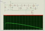
anyway, white noise was put into the circuit, this is the output (cant seem to convert to logarithmic scaling).
anyway, frequency response... see attached
 

Attachments

QuIcK

Senior Member
the trouble with that is a picaxe cannot sample adc fast enough to "view" the audio spectrum. sampling alone takes ~10ms, without the maths to do a fourier transform in order to weight the frequencies
 

boogiebehometh

New Member
headroom?

Nice find on the A-weighting filter, Quick...

i'm excited how this is getting on...

the trouble with that is a picaxe cannot sample adc fast enough to "view" the audio spectrum. sampling alone takes ~10ms, without the maths to do a fourier transform in order to weight the frequencies
U can solve this by popping well-designed envelope filter in each channel... This may take the form of a full-wave rectifier & an carefully selected lpf....

but quick just reminded me... if u're gonna use the onboard ADCs, they're 10-bit ones, which means u're getting ~1000 discrete = 60dB of digital headroom... - if i still remember how to do it correctly...

- that's provided your analogue signal perfectly maximized to the optimal level, which, is again, another hurdle...
 

Tom2000

Senior Member
Having been down this road (well, not with this exact problem, but lots of home metrology stuff over the years), the problem of calibration and calibration verification, short and long term accuracy, and response time pop right up in front of my mind's eye, raising all sorts of red flags.

Considering the cost of cobbling up the front end, then endless iterations to gain the performance you need, this is one case where an off-the-shelf solution will be more cost effective, and particularly time effective, than a roll-your-own solution.

SPL meters are pretty cheap these days. Some inexpensive SPL or Sound Level Meters even have outputs suitable for connection to a logging system.

I know that a commercial solution would take a lot of the fun factor out of your project, but building a suitable back end logging system for the commercial front end meter will probably provide enough fun, and in the long term, guarantee that you'll arrive at a workable system within your lifetime.

Here's an example -- one of many -- of an inexpensive SPL meter with an output that can drive a logging system:

http://www.reliabilitydirectstore.com/Sound-Level-Meter-p/rdi-ar824.htm?gclid=CIjb9ryOiZoCFSMSagodpRhJFg

Do your own Google search, and check your local sources, for a meter that meets your requirements and budget. (Search for both SPL meter and Sound Level Meter.)

Good luck!

Tom
 

eclectic

Moderator
It's Tom's fault. :))

I received one of these today (Sat.)
http://www.amazon.co.uk/Silverline-633937-Sound-Level-Meter/dp/B0015NSTLI/ref=sr_1_1?ie=UTF8&s=diy&qid=1240683743&sr=8-1

There's an RCA socket on the side.
The sparse instruction sheet states
“Signal output 1.0V (peak)”

I did a few quick un-scientific tests.

1.
S/M. Range setting = 90 dB. Slow response. A weighting
AC setting on the DMM.

Quiet – loud whistling produced voltages between 0v - 3.5v.

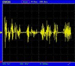
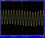
2.
Connected to my cheapo 'Scope.
Pic 1. Whistling a tune.
Pic 2. My best attempt at a single note.

Some possible thoughts.
A four-diode full wave rectifier?
Capacitor smoothing?

e
 

Attachments

Last edited:

rmeldo

Senior Member
I love this forum.

People even buy hardware to answer your questions !!!

Now that the interfacing and dBA weighing is proven the problem of catching the sound level between spikes still remains.

If I understant it correctly the sound has components up to 20kHz so (Niquyst) it needs to be sampled at 40 kHz to capture the sound level correctly.

Or have some kind of circuit (probably analog) which stores the peak reached during the sampling interval (say 200 ms). The Picaxe should them be able to handle it.

Am I talking nonsense?

Riccardo
 
Top