how to I2C

rob nash

Senior Member
hello again,
am still working on my led chaser am using an 20x2 to control 9 led that part is going well. making varies subroutine for different sequences
what am struggling with is how to activate the varies subroutine

i have a 40x2 which is the master picaxe and i thought using the I2C
but am struggling to see how to implement this idea infact hit a mental wall
would someone kindly give a code sample PLEASE O PLEASE of how master and slave should look too get an led plinking on the 20x2 slave or guide me in the right direction.

i thought it would be of case master writes a variable in the slave somewhere the slave looks up the variable then would go to a subroutine
and that as far as can visualise

not even sure if I2C is the right way to go?,
any advice would be helpful cheers rob

PS i do read the manuals still do, just takes months for it to sink in.
 

eclectic

Moderator
hello again,
am still working on my led chaser am using an 20x2 to control 9 led that part is going well. making varies subroutine for different sequences
snipped
PS i do read the manuals still do, just takes months for it to sink in.
Please post

1. A schematic of what you have, so far.

2. Any program that you have, so far.

3. Say five short sentences, which describe

exactly what you want to achieve.

e
 

BeanieBots

Moderator
You're on the right track.
When a PICAXE 'talks' to another PICAXE via I2C, it does so just as if it's an EEPROM. The master puts data into the scratchpad of the slave. The slave will have a flag set indicating that new data has arrived which it can then go off and read either as an interrupt or at it leasure.

Is it the way to go? Only you know what you want it to do.
Personally, I would have thought a few push-buttons on a few pins would do nicely and be much easier to implement.
 

rob nash

Senior Member
hi
what am aiming to do is have the master 40x2 trigger the 20x2 which is going to be my cylon eye on my little bot or any led sequence.
as for a program having real trouble getting this one started.

been thinking of using an output from the 40x2 to the input of the 20x2
as a trigger but if i can use I2C setup then i can have few different displays thats the plan.
 

rob nash

Senior Member
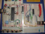
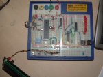
the two pic is where am upto on the lft 40x2 with the EEprom at the bottom the 20x2 on the lft with a 330 resistor array i dont have the scl /sda on the 20 connected to the bus line yet. the chip in between picaxe's is an uln2803 i thought of using it to switch the 20x2 on when needed.
rob
 

Attachments

Last edited:

eclectic

Moderator
OK rob, just checking here:

Each "eye" has eight LED's, flashing
1, 2, 3, 4, 5, 6, 7, 8, 7, 6 ................. ?

And, each one is controlled by a single 20X2?

Further, all the "Eye controllers"
are controlled by a 40X2 "brain"?

Have I got the message so far?

e

Oh! Just seen that your post has changed.
 
Last edited:

rob nash

Senior Member
hi eclectic
yes that its one row of led 1 to 8
controlled by the 20x2 which is to triggered by the 40x2 "brain"


this is the program am running on the 20x2 at present


symbol led1 = c.5 'set the pins for 330-red led
symbol led2 = b.6
symbol led3 = b.4
symbol led4 = b.3
symbol led5 = b.2
symbol led6 = b.1
symbol led7 = b.0
symbol led8 = c.7


symbol abit = 100
symbol abitx = 70
symbol counter = b1

init: hi2csetup i2cslave, %10100000
gosub split
pause 10

main: pause 10
gosub cylon
pause 100
high led2
high led6
pause 1000
low led2
low led6
pause 1000
goto main


split:
for counter = 1 to 4

high led4
high led5
pause abit
low led4
low led5
pause abit
high led3
high led6
pause abit
low led3
low led6
pause abit
high led2
high led7
pause abit
low led2
low led7
pause abit
high led1
high led8
pause abit
low led1
low led8
pause abit
high led2
high led7
pause abit
low led2
low led7
pause abit
high led3
high led6
pause abit
low led3
low led6
pause abit

next b1
return


cylon:
for counter = 1 to 4
pause abitx
high led1
pause abitx
low led1
pause abitx
high led2
pause abitx
low led2
pause abitx
high led3
pause abitx
low led3
pause abitx
high led4
pause abitx
low led4
pause abitx
high led5
pause abitx
low led5
pause abitx
high led6
pause abitx
low led6
pause abitx
high led7
pause abitx
low led7
pause abitx
high led8
pause abitx
low led8
pause abitx
high led7
pause abitx
low led7
pause abitx
high led6
pause abitx
low led6
pause abitx
high led5
pause abitx
low led5
pause abitx
high led4
pause abitx
low led4
pause abitx
high led3
pause abitx
low led3
pause abitx
high led2
pause abitx
low led2
pause abitx
high led1
pause abitx
low led1
pause abitx

next b1

return


cheers rob
 
Last edited:

hippy

Technical Support
Staff member
i thought it would be of case master writes a variable in the slave somewhere the slave looks up the variable then would go to a subroutine
and that as far as can visualise
That's about it. I2C write from the master, the I2C slave receives that in a scratchpad location, the program reads the scratchpad location then chooses which routine to execute based on the value retrieved.
 

westaust55

Moderator
@Rob,

firstly, can you try to use the [code] and [/code] markers around you code so that it appears in a scrolling sub window within your post. Lot easier on the eye for those scrolling down the pasge.

Secondly, how committed are you to the use of two 20X2 chips for the eyes. :confused:

Could be worth considering a single MCP23017 i2c IO expander which will give you two 8-bit bidirectional ports. Particularly if the main chip has room for the extra code. Otherwise one PICAXE (even a smaller 18X) with i2c comms could be used s the slave device.

One MCP23017 chip could handle both 8 LED eyes and writing one byte would do the same as four HIGH/LOW commands you are currently doing.
Two consecutive bytes in one i2cwrite type command will set both eyes to a new "position".

Then instead of code using 18 bytes such as:
Code:
high 1
high 2
pause 100
low 1
low 2
pause 100
high 3
high 4
pause 100
you would have lines using just such as
Code:
 HI2CSETUP I2CMASTER, %101010100, i2cfast, i2cbyte
:
:
:
hi2cout  ($18)
pause 100
hi2cout  ($24)
The HI2CSETUP is only needed once and the two write statements occupy just 9 bytes.

A total of just 3 bytes more for
Code:
hi2cout  ($18, [COLOR="Red"]$18[/COLOR])
pause 100
hi2cout  ($24, [COLOR="Red"]$24[/COLOR])
which would be controlling both eyes


The MCP23017 is currently available at
www.futurlec.com.au for AUD$1.26ea
www.futurlec.com for US$1.20ea
 
Last edited:

rob nash

Senior Member
hello again
westaust55 am using the 20x2 because i have it at hand, and I'll be looking into MCP23017 chip but was'nt thinking of a i2c IO expander at the mo. learning how the I2C bus work and to have the picaxe share data.
and am really struggling. my apologises to forum members for my messy threads will attempt to compile my question more tidy in future.
anyhow would someone please telll me what am missing


this is the master
Code:
'I2C master test


symbol wp = d.4
symbol R_led = d.7
symbol G_led = d.6
symbol  topline = 128
symbol bottomline = 192
symbol screen = 254

symbol lcd = d.2
symbol abitx = 1000
symbol abity = 100


init:


    hi2csetup i2cmaster,%10100000 , i2cfast,i2cword
    pause abity


 main:

   pause abity
      readadc 1,b12
      if b12 < 100 then cylon

      pause abity
    serout lcd,n2400,(screen,1)
      serout lcd,n2400,(screen,bottomline,"  10Kpot ",#b12,"    ")
      pause 1000
      goto main


cylon:
     low R_led
      high G_led
      serout lcd,n2400,(screen,topline,"    sending    ")
       hi2cout [%10100000],0,(b12) 
                                                          
       pause 3000
      serout lcd,n2400,(screen,bottomline,"  10Kpot ",#b12,"    ")
      pause 1000
      goto main
the program appears to be working fine i am unsure if am sending data.

my slave program missing something
Code:
'I2Cslave setup

symbol led1 = c.5        'set the pins for 330-red led
symbol led2 = b.6        
symbol led3 = b.4
symbol led4 = b.3
symbol led5 = b.2
symbol led6 = b.1
symbol led7 = b.0
symbol led8 = c.7


symbol  counter = b3

symbol abitx = 1000
symbol abity = 100

init: hi2csetup i2cslave,%1010000  
        pause abity
        
main:
    high led4
    high led3
    pause 100
    hi2cin [%10100000],0,(b12) 
   get hi2clast,b12
    if b12 < 100 then cylon
    pause 100
    goto main
              
cylon:
      low led4
      low led3
    for counter = 1 to 4
    high led1
    high led8
    pause abitx
    low led1
    low led8
    pause abitx
    next b3  
    goto main
the slave program never runs the subroutine have i got this completly wrong
advice please
rob
 

rob nash

Senior Member
good day
anyone point me in the right direction i can't see where am going wrong am still working on the programs in my last post, and the manuals are begining to blurr.
cheers rob

"it has been said it's easy to teach a donkey phonics, than teach me anything"
 

hippy

Technical Support
Staff member
Take a step back and write much simpler programs to get an understanding of I2C. For the master just have that sending an increasing number every second, for the slave report that received number with SERTXD, and then you can improve that code and only report when it changes.

Something like ...

Sender:
HI2cSetup i2cmaster, %11100000, i2cslow, i2cbyte
Do
Pause 1000
HI2cOut 0,( b0 )
b0 = b0 + 1
Loop

Receiver:
HI2cSlave %11100000
Do
Get 0, b0
SetTxd( #b0, " " )
Loop
 

rob nash

Senior Member
thanks hippy

i have this setup running and somthing happening


Code:
HI2cSetup i2cmaster, %11100000, i2cslow, i2cbyte
Do
Pause 1000
let b0 = 10
HI2cOut 0,( b0 )
b0 = b0 + 1
Loop

Code:
 init: hi2csetup i2cslave, %11100000
Do
Get 0, b0
SerTxd( #b0, " " )
Loop
in the terminal window from slave 20x2 the input buffer reads like this " --yyyyyyyy--yy--aaaa--" i was expecting a number value even thoe i did,nt assign b0 with one, i thought it would run fom 0 to 699999990
should it be this way
more advice please rob

"just read back post and did assign the value 10 to b0 on th master, after posting ,still i don,t think it makes much of diffrent at this stage but will rmove and see"
 
Last edited:

westaust55

Moderator
i was expecting a number value even thoe i did,nt assign b0 with one, i thought it would run fom 0 to 699999990
should it be this way
more advice please rob
Have not looked into your code at this time of day (wee small hours) but you mention b0 and values to to 699,999,990 in the same sentence.

a byte variable such as b0 can have a value from 0 to 255
a word variable such as w0 can have a value from 0 to 65535
PICAXE cannot handle larger values without you using some routine of your own to maninulate larger values such as double words (= 32 bits)
 
Last edited:

hippy

Technical Support
Staff member
The problem I overlooked in my code ( apart from the typo's ) is that because it's almost always in SERTXD, that can lock-out interrupts so the I2C write cannot be handled correctly. I suspect the "--yyyyyyyy--yy--aaaa--" error may be baud rate but not sure what code you were running there.

This works for me, 28X2 sender to 20X2 receiver ...

Code:
#Picaxe 28X2
#No_Table
#No_Data
#Terminal 9600

Sender:
  HI2cSetup i2cmaster, %11100000, i2cslow, i2cbyte
  Do
    Pause 1000
    HI2cOut 0,( b0 )
    SerTxd( "Sent ",#b0, CR, LF )
    b0 = b0 + 1
  Loop
Code:
#Picaxe 20X2
#No_Table
#No_Data
#Terminal 9600

Receiver:
  HI2cSetup i2cslave, %11100000
  Do
    Get 0, b0
    If b0 <> b1 Then
      b1 = b0
      SerTxd( #b0, " " )
    End If
  Loop
Make sure you have pull-ups on SDA and SCL, connections to the right pins and not swapped over.
 
Top