How many ways are there to reset a picaxe?

Tyro

Member
How many ways are there to reset a picaxe?

I have a picaxe system that works, as designed, perfectly but keeps resetting itself randomly. It does this at a rate of once every 48 hours to about once every 2 hours.

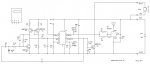
I have previously built over 100 of these systems without this problem. The last batch consisted of a new artwork, new wireless transmitter module and used a 08m2 picaxe instead of the 08m I had used previously. It is powered by 3 AAA cells, decoupled by a surface mount 0.1uF ceramic capacitor very close to the 08m2 Vcc and 0v pins and with a 33uF bulk capacitor. The new wireless transmitter module was disconnected early in the investigation. Pin 2 (serin) was initially connected to 0v via 10k but the resistor has been shorted out.

20 of the units were built and the power to them were all wired in parallel to a reliable, stabilized power supply to eliminate intermittents in the supply source.

The software works by going through an initialization section which beeps at the beginning and beeps for a second time at the end of the initialization section then goes to the main: portion. In main: it calls a number of other sub routines and cycles round these including a sleep1 command. It is not possible for the initialization section to be restarted. The disablebod and enablebod have been removed and disablebod added at the end of the initialization section.

The circuit and software are essentially the same as the first 100 units with only minor changes.

I added a little routine to the initialization section which counts and stores to EEPROM the number of starts the unit has made and using debug transmits this number whenever the chip is repowered.

I have determined the worst and the best boards then swapped the chips to see if the problem is the board or the chips. No consistent result occurred; the fault rate was still random.

How many ways are there to reset a picaxe?
 

srnet

Senior Member
"The circuit and software are essentially the same as the first 100 units with only minor changes."

What were those changes ?

Circuit diagram ?
 

hippy

Ex-Staff (retired)
How many ways are there to reset a picaxe?
An interesting question. Things I can think of are ...

Power interruption or brownout, excessive current draw collapsing supply, an 'external event' triggering reset ( EMI, RFI, electrostatic discharge etc ), over driving input pin voltage or excessive injection current, negative input voltages perhaps.

Configuring ADC with Vref voltages which cause clamping or other excessive current events. Injecting analogue signals into digital inputs ( Microchip have never been entirely clear on the consequences of that on any PICmicro ).

Issuing a RESET command, a POKESFR to somewhere iffy, or a GOSUB-RETURN stack underflow perhaps.

Raising Serial In to a high without a DISCONNECT command.

Probably more that I can't at this time think of.

What's perhaps most interesting is that there's no consistent or obvious systemic failure mode which suggests it is ( or related to ) an external event of some kind, not a program flaw, and by extension not a firmware flaw.

My crystal ball is suggesting adding a DISCONNECT command as the most obvious injection point for a signal which can intentionally reset a PICAXE is through the Serial In. Adding that will either improve the situation or not which is useful to know either way. However you don't seem to have a programming connection.

Beyond that it would perhaps be a matter of testing stability of the system with just a simple loop and the reset counter diagnostics to see if that's robust or suffers the same problem. If it is robust then expanding that code to see what causes it to become more prone to resets.

One thing to remember is that an affect on 0V can be the same as keeping 0V rock steady and affecting something else. I had a bizarre situation where things would not work when my soldering iron was turned on but would if turned off and some people have reported fluorescent lights affect their circuitry.

It may be worth posting your circuit diagram, your code and any useful photos just so others can at least say, yes that should work okay, or identify any potential problems.
 

hippy

Ex-Staff (retired)
"The circuit and software are essentially the same as the first 100 units with only minor changes."

What were those changes ?
Very good point, and also worth testing an older 08M with the earlier code on these boards to see if it's a circuit, component or assembly issue rather than a software or PICAXE related issue.
 

Dippy

Moderator
Can we assume that your device was 100% OK with 08M and now showing a random reset with 08M2?
And it does it happen regardless of whether using batteries or PSU?

"Pin 2 (serin) was initially connected to 0v via 10k but the resistor has been shorted out."
- do you mean that on your original OK boards this was a 10K pull-down , but on your recent faulty boards this was directly grounded?

Does it reset (albeit randomly) at the same place in code?

Do you have any nearby noisy electrical items switching? (e.g. fluorescent tubes or aircon or anything nasty?)

Does it reset with all references to BOD removed?

Does it reset if you just put some basic cut-down code into 08M2 in same circuit board?

Have you 'scoped power pins and inputs to see if any nasties are coming in from somewhere?

Have you tested recent code in old 08M config?

Circuit and code please. (You just knew it was going to be asked for :) )
Including links to any special components.
 

John West

Senior Member
Well answered, (post #3) Hippy. I had contemplated an answer of "At least 5," as a valid response to the question posed, but thought better of it (but not so much better as to make no mention of it. ;) ) This appears to be an interesting and less than obvious problem, and there's really no way to provide a helpful answer without an in-depth look at both the circuitry and the code.

In general, I've taken to ignoring problem-solving threads where the code and circuitry are not provided. Not sure what posters think we can do without real info, but shooting in the dark gets old quick.
 
Last edited:

Tyro

Member
Answers to Dippy’s questions.

It was OK with 08M but not working with 08M2. I am about to try some old 08Ms in the new board.

It happens with either batteries or stabilized supply.

Pin 2 was connected via a 10k resistor on both old and new boards. It was just shorted due this investigation. The results showed no change.

I do not know where it fails in the code, it just restarts again. When the chip is re-powered connected to a PC, the debug in the initialization section indicates the number of restarts that has occurred.

There is nothing noisy; it is in an electrically quite environment.

Enablebod is by default on but recently I have disabled it after the initialization section finishes. No affect.

What I am using now, attached to this reply, is stripped down code.

I have scoped the supply pin with both an analog scope and a digital one set to trigger and store. Nothing.
Sensor MK3-1+4.5V RF.JPGView attachment MK3-1 CODEmin code+snooze+measure+logic_No_test reset test.BAS
 

hippy

Ex-Staff (retired)
I couldn't see anything in the code which would likely cause a reset nor in the circuit except that I'm not sure how Cx, C1 and D1 are being used. These seem to be driven by a PWM; if a C ends up with +5V on both plates, then pulling one plate down to 0V sets the other at -5V with respect to that 0V, doesn't this then dump -5V into 0V ? I may have got that all wrong with what actually happens in the circuit but it's an area which attracted the attention of my eye.

From the description I'd guess this is a water presence detector putting putting AC / PWM through the sensor but perhaps you could clarify what it's doing. What's Cx replaced by when testing ?
 

Tyro

Member
Cx is a distributed flat capacitor that when it becomes wet, its capacitance increases. The PWM output consists of a series of short positive pulses which charges Cx to Vcc minus 1 diode drop, (D1). C1 is a large dc blocking capacitor and is not important in understanding the circuit.

When the PWM output returns to 0v the left hand end of R1 goes negative, returning to +1 diode drop exponentially. The average current, which is proportional to Cx, is averaged by C2, R2 and eventually measured by the ADC.

At the moment I have a batch of 20 units running from a stabilized supply. Seven of them are using 08M devices, all I could find. The remaining 13 are running the same software using 08M2s. Because of the long time between resets, multiple units have to be run over 24hours to get any meaningful data.
 

hippy

Ex-Staff (retired)
When the PWM output returns to 0v the left hand end of R1 goes negative
Thanks; that's the sort of thing I was thinking could be affecting things.

For example; where does that negative current go ( or come from ) ? It could be causing ringing somewhere, overshoot or undershoot and that could be destabilising the PICAXE, especially if it occurs at the point the PICAXE may be switching an output / PWM when current draw will increase. If Sod's Law is performing as expected then putting a scope on any iffy signals will improve them so it can be hard to see what's actually happening.

You haven't said what's on Cx when testing; C1 could be acting as an aerial if left unconnected.
 

Tyro

Member
Cx is about 100pF when dry and 2 to 300pF when wet. During these tests, the dry sensor is Cx. The worst current is when the positive pulse occurs and Cx is charged up. What limits the peak current is the current limited output from the PWM pin. The cathode of D1 is very close to the 0v pin of the chip and the 0.1uF decoupling capacitor.

The tests are taking place in the basement of a rural house with no one living in it. The only thing operating is a small fridge physically far away.

The peak negative current is limited by R1 to about 4v/27k = 0.15mA.

Last night I said I would use some 08Ms I had and use the code I posted. Unfortunately that code used word registers above W6 and could not be used with the 08M. I judiciously changed the code and deleted w7, w8, w9. Not everything was required for this truncated test code.

I used exactly the same code for the 08M2 as for the 08M. In the morning not one had reset. I then used the full code, the one which results in my reset problems. I carefully modified it to only use w0 to w6 and programmed half the batch of with the original code using w0 to w9 and the other half with the w0 to w6 code.

Tonight, after work, I checked how many had reset. One of the units with the original code had had a single reset. This not statistically good enough to draw any conclusions. From earlier experience I believe 48 hours will be required to generate enough data.

Please be patent.
 

hippy

Ex-Staff (retired)
What limits the peak current is the current limited output from the PWM pin.
That might be part of the problem; PICmicro outputs don't have current limiting. They have maximum output ratings but that's a "draw more than this and you are damaging the chip" warning. There's nothing automatic which will stop more current being drawn from an output pin than the safe maximum ... except supply voltage collapse ... which could be a cause of reset.
 
Top