how do I add a switch to the input pins on the sd21

I want to add a switch to my sd21, just for a basic high/low, on /off function. I can't post the code I tried as I'm on the work computer, but when I tried adding a switch and tried downloading the program I was told 'Hardware pins have not been set up to use these commands'. I can play around with code as I experiment, but what actual input pins on the sd21 should the wires from the switch be connected to?
 

inglewoodpete

Senior Member
Without seeing your code, it's hard to double guess where you are going wrong.

Firstly, I assume your PE can communicate with the PICAXE chip. (Do a firmware check to confirm this.)

  • You can only use input pins as inputs (funny thing, that ;)).
  • You must address the input pins indirectly to 'see' their state. Eg If pinB.3 = 1 Then ....
  • Make sure your code is looking at the correct hardware pin (we like to call them legs). Refer to Manual 1 for leg numbers versus the virtual pins. (08M2 pin out diagrams)

I hope this helps. Edit: Hmm The SD21 is the AXE031 rather than the AXE021. So substitute 18M2 above.

Peter
 
Last edited:

hippy

Technical Support
Staff member
when I tried adding a switch and tried downloading the program I was told 'Hardware pins have not been set up to use these commands'.
If using Logicator you may need to use Options -> Select PIC Type and Configure I/O.

Some more detail as to what you are using, which PICAXE, and whether that's the PICAXE on the SD21 board or a PICAXE controlling the SD21 board will help.
 
the sd21/axe031 comes with a 18x chip. The axe031 manual shows how the chips legs are numbered and how the 16 pin header is numbered, so what I need to know is what pins on the header do the red and black wires of the slide switch do I connect to?
 

westaust55

Moderator
@jonny,
It would help if you provided your version of the connection diagram and the code you are using rather than folks here trying to start from scratch without your project in front of them.

Is the slide switch a simple on/off switch with two terminals or a change-over switch with three terminals? Keep in mind you can see the slide switch but we cannot so a diagram of photo helps a lot.

Where are the red and back wires connected? Who connected them?
Red is usually for the positive supply (5 Volts) and black for the ground (0 volts) so confusion may arise just saying where do I connect red and black wires.

From a glance at the AXE031 Datasheet there are no pull-up or pull-down resistors on the PICAXE chip IO pins. Therefore particularly if you have a simple on/off switch you will end a resistor to stop the input pin floating when the switch is open giving erroneous input values.

Suggest that you look at PICAXE manual 3
http://www.picaxe.com/docs/picaxe_manual3.pdf
Page 26 provides schematic showing how to connect a switch as an input device.

Look at PICAXE manual 1 page 9 for the 18X pin out diagram.

The AXE031/SD21 has inputs at the 16pin header identifies as
iNP0, INP1, INP2, INP6 and INP7.
Let's say you connect to header pin 2 which is INP1. That goes to input1 on the 18X.
So then you need a program command such as
iF pin1 = 1 THEN ..
 
Last edited:
I'll show you the code then explain what I'm trying to do, I've also discovered that apperently the 18x is no longer used or supplied with the sd21, its actually a 18m2, so its the diagram for a 18m2 I've been going by while trying my inputs.
Code:
symbol servo1 = 63
symbol servo1p = 84
symbol servo1n = 105
symbol servo5 = 67
symbol servo5p = 88
symbol servo5n = 109
symbol base = 128
symbol offset1 = 0
symbol offset2 = 200
init:
if pinc.5 = 1 then goto progstart
gosub idle
progstart:
hi2csetup i2cmaster, $c2, i2cslow, i2cbyte
main:
writei2c servo1p, (offset1)
writei2c servo5p, (offset1)
pause 5000
writei2c servo1n, (offset2)
writei2c servo5n, (offset2)
pause 5000
goto main
idle:
hi2csetup i2cmaster, $c2, i2cslow, i2cbyte
writei2c servo1p, (offset1)
writei2c servo5p, (offset1)
end
[code]
I had a slide switch with the red wire (5v+) connected to pin 12 (should be c.5 on the 18m2) and 0v to pin 10. The idea was that should the switch be high the servos would do the 'main' routine, going from one end to the other (0-200); and if low, going to what I call the 'idle' position (both servos at 0). However, when downloaded, the switch didn't seem to be recognised, servos just kept doing the routine in 'main' no matter what I did with the switch. I did try adding the resistor like was suggested. What if I used a DPST switch, as in on-off-on. On1-it goes to progstart, on2- it goes to idle, off-off/shutdown?
 
Still haven't got very far with this, really need to know how 16 pin headers match up with the 18m2 and how to add a dpdt switch. Very close to finishing my project, just need to add this switch. Please help.
 

eclectic

Moderator
Please see Westy's comment from post #5

"Is the slide switch a simple on/off switch with two terminals or a change-over switch with three terminals? Keep in mind you can see the slide switch but we cannot so a diagram of photo helps a lot."

What sort of switch do you have?

e
 

rossko57

Senior Member
really need to know how 16 pin headers match up with the 18m2
The SD21 documentation
http://www.picaxe.com/docs/axe031.pdf
describes the 16-pin header pins available.
But as you noted earlier, the document was written with Picaxe 18X in mind and describes pins as INP6, OUT5 etc.
Obviously those are Input-6 and Output-5 in Picaxe terms.
Looking at Manual 1 page 32 we can see the pinout for an 18X and match up OUT5 to chip leg 11 on an 18X and so on, though we generally don't care as the SD21 PCB designer has alreadt taken care of that.

As you also noted earlier, you may have an 18M2 not an 18X (have you found for sure yet, using program editor?)

Again looking at Manual 1 page 32 we can match up chip legs i.e. leg 11, which is labelled OUT5 on the SD21 board for 18X, would be pin B.5 in 18M2 terms. So far so good.

I had a slide switch with the red wire (5v+) connected to pin 12 (should be c.5 on the 18m2)..
errm, which pin 12? Pin 12 on the SD21 16-pin header is labelled OUT7 (for an 18X) which would be Picaxe leg 13, which for an 18M2 would be be B.7 not C.5

Picking an easy substitute, SD21 header pin 1 is marked INP0 which would be Picaxe 18X leg 17. 18M2 leg 17 is pin C.0
You could rewrite your code to look at C.o, wire your switch between header pin 1 and a convenient ground.

I don't think there is a pullup resistor on the SD21 to ensure the input is truly "high" when floating, so you might want to add code to use the PULLUP command available on 18M2
 
This is the dpdt switch (on/off/on) I want to use on the sd21, conveniently the legs are lettered in the photo. I figure that I need to be connected to two inputs and a ground on the 16 pin header (do I need to be connected to V+ since the sd21 is powered anyway??) using perhaps pin 12 for b.7, pin 11 for c.0 (as for 18m2) and pins 15/16 as ground. So how do I wire up to the switch?images.jpg
 

westaust55

Moderator
Okay so from the photo in post 10 now we know that you have a DPDT (on/off/on) type TOGGLE switch.

As I see it if you only want a high/low input to a single PICAXE input then you wire across/to two from one pole of the toggle switch.
The switch you have is seemingly overkill for such a purpose but can be used. It would in effect be used as on/off/off.

Maybe if you can sketch up a simple diagram depicting how you want to use the switch and what is expected for each of the three available positions folks could better understand what you are trying to achieve and then Give you a clear answer as to how to wire the switch.

It could be as simple as:
From 5 volts, through a 10 kOhm resistor to switch connection "C"
From 0 volts directly to switch terminal "A"
Then also from "C" to a PICAXE input - via a 1 kOhm resistor to be safe
That in effect uses the switch as a SPST switch connected as per the diagrams in PICAXE manual 3.
 

Paix

Senior Member
@JohnyMelon,
Code:
AXE031 (SD21) datasheet page 3
16 pin header top view reflecting use of Picaxe 18M2

    16      15
Gnd []      [] Gnd

N/C []      [] N/C

B.7 []      [] B.6

B.5 []      [] B.3

B.2 []      [] B.0

C.7 []      [] C.6

C.2 []      [] N/C

C.1 []      [] C.0
     2       1
This is the socket and reflects the greater flexibility which the 18M2 offers in terms of input and output capability. When choosing a pin for your switch, consider what other functions on that pin which you may be sacrificing.

I can see from your statement “if pinC.5 = 1”, why you originally chose PinC.5, because it was just an input pin, but as has been pointed out, that pin is not extended to the 16 pin header. Your intention was also clear that the switch in the open.non-operated state was to allow your input pin to be pulled low.

Look at Manual #1 page 10, choose which of the pins extended to the header you wish to use, heeding the advice in my last paragraph, and with the switch in the non-operated state, connect as follows:

Code:
B []    [] A
    |..|   
D []    [] C

F []    [] E

Switch toggle up, unoperated state
 = AC closed CE open. BDF spare/unused switch
Terminal “C” to +ve rail and
terminal “E” 10k resistor to Gnd

Also terminal “E” 1k resistor to your chosen port.pin on the 16 pin header.

Only terminals C and E are actually used so they are interchangeable, in this instance.

= = =
I feel that the documentation for AXE031 should be updated to additionally reflect use of the 18M2, which was a good part of the confusion in this post. That doesn't let you off the hook though Jonny . . . :)

Are you all clear now?
 
Last edited:

westaust55

Moderator
Note that in post 12, I have used terminals A to C and a pull-up resistor. Could just as easily have used switch terminal E instead of A.

At post 13 Paix has used switch terminals C to E and a pull down resistor.

As you can see, when you ask for help there can be many ways all with valid answers but may lead to your confusion as to how to proceed determining which you think is right.
 

Paix

Senior Member
You are right Westaust55 and I didn't seek to contradict you, but failed to read your post comprehensively. Sorry. :) It seemed that the carcase had been well mauled before your post.

JM appeared confused and, had the AXE031 documentation been brought up to date to reflect that it is now supplied with an 18M2, then it would just have been a how do I wire the switch problem. Indeed the board sounds quite useful but obviously there are more important things going on just now.

I signally failed to pickup on the switch contacts that you had suggested and if I had been a little more astute I would have noticed and gone with the flow instead of suggesting the alternative contact set. I had picked up that JM wanted the pin to be active high and so did go with that.

Hopefully JM has the message, one way or another and someone at Rev Ed will find a little time to squeeze the alternative pin header description into the AXE031 datasheet to clarify things for potential users who might otherwise have difficulty making the proper connection.

To myself, not familiar at all with the terminal nomenclature used with the Picaxe 18X, the labelling of the header initially appeared to refer to attributes of the AXE031 and not necessarily the chip hosted by it. By that time I had Manual #1 open at pages 9 and 10 for chip pinout comparison, the AXE031 datasheet for the pin header diagram and quickly scanning the complete thread for what may have been solved already. With the exception of your own response, I wasn't really convinced that JM was going to be sufficiently tuned in to solve his problems.

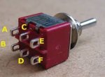
Sometimes when you don't know how to do something and the subject is relatively new, then it is difficult to concisely express the problem and so we end up with a lot of noise as well as the pearls, missing the multiple natures of the difficulty being experienced; namely how to configure a switch (schematically) or in this case a specific switch. The header pin layout wasn't explicitly queried, to the best of my recollection (I'm typing so won't try to go back and look) but I figured that it was a significant stumbling point.

Something in this thread for all of us and not just JM perhaps? :) As a regular noise maker, should I be tiptoeing quietly towards stage left?

I did stop to consider my perceived toggle switch conventions - US down is OFF (can be slammed down in an emergency), UK down is ON - well it used to be a few aeons ago!

Is it working now JM and if not what do you need to know. Your public awaits!
 
Last edited:
wow, I better start getting results or I'll never live it down. Definitely, a diagram of the pin header layout for the sd21/18m2 from rev-ed would have helped at the start. When I mentioned pins c.0 and b.7 that was only because rossko57 had Identified them for me. Anyway, it might be the end of the week before I get the time to get any work done on my project so I'll just outline what I'm trying to do again. The code in post #6 has two routines, progstart and idle (this code was just for experimenting, I eventually want to write a code for a 7 servo robot arm),and the plan is that when the switch is in the ON/off/on position the arm will preform 'progstart' and when the switch is at the on/off/ON position it'll preform 'idle'. I once mentioned in a previous thread that I compared my arm to the type you see in a car factory, ie: car comes along, arm preforms a set routine of spotwelding (progstart), while waiting for the next car the arm settles down as if resting (idle).
Thats basically all I want the arm to do, a programmed set of movements that I can interrupt at the flick of a switch telling it to settle back into a kind of 'out of service' position.
 

adamg

Member
Hi, I am having a similar problem. I guess I should had started with something easier. The diagram of the pins provided by paix! GREAT HELP! Still having trouble adding a micro switch to the board.

I don't want to hijack your thread here - but people can answer my question, it might help us both :)

Here is my nasty ugly code >__< As a test, I have had no problems moving the servos. Now - How can I move them with a microswitch? Sorry for my basic BASIC.. Any ideas? When I run this, the servo just starts moving without a switch even attached!


Code:
i2cslave $C2,i2cslow,i2cbyte ' Join i2c with SD21                                                   
          
          main1:
          	if pinc.1 = 0 then
          		goto main1
          	endif
          	
          	if pinc.1 = 1 then
          		goto main2
          	endif
          	
          Main2:
            i2cwrite 0,(10)	    ' speed  1 - 100
            i2cwrite 63,(225)        ' Set servo 1 to 255 
            pause 3000
            i2cwrite 0,(10)             ' speed  1 - 100
            i2cwrite 63,(110)         ' Set servo 1 to 110
            pause 3000    
 
       goto main1
 

westaust55

Moderator
@adamg
Do you have a pull-up or pull-down (up or down as necessary) resistor on the input to which you have the switch wired.
This is needed to stop the input floating otherwise when the switch is open, the input can still be in the star state as when the switch is closed. See PICAXE manual 3 for input switch schematics with resistors.
 

adamg

Member
@westaust55

Thanks for the reply. I looked into resistors. I had no idea one was needed, so did some tutorials and read lots today. I think if I use a pull down resistor, it should help. I had only ever used a project board with built in resistors before. Now I feel like I'm using a grown-ups board hehe.

You're a superstar mate! Thanks for guiding me in the right direction!
 

Paix

Senior Member
Additional info:

Traditionally the value used for pull up/down resistors is 10k. This is a value that will limit the current to 0.5mA should a normally closed switch be used when using a +5V supply. A normally open switch is more common as there is no residual current drain. A higher value resistor will give a weaker pull up and a lower value a greater residual or operating current drain when operated. So 10k is a GOOD value.

Additionally, increased protection against programming errors and oversights can be employed. A resistor value between 330R and 1k is suitable to limit fault current to between 15mA and 0.5mA.

It should be said that in general use such a current limiting resistor is superflous, but if there is a possibility of you making a programming error which defines the port.pin as an output, then it may be worth the trouble.

So, what is the risk? If you take good care then the risk is minimal, which is why it is not a generally standard practice. The risk is increased if you are using a normally closed switch.

What is the nature of the risk? The risk is that a port.pin is inadvertently programmed as an output, which in the worst case of a normally closed switch would cause a short to either ground or the positive rail, with attendant possibility of destruction of the port.pin or the chip. The inclusion of a current limiting resistor won't make your code work any better, but might save a little smoke.
pullupexample.png
Hopefully this will be of interest or use.
 
I've rigged up my switch to the sd21 along the lines of fig B in PAIX's thread and it seems to be connected correctly, however the code probably needs tweaking. Last night I was able to switch it one way and it preformed the 'progstart' routine, switched the other way it did the 'default' routine, switched to middle it did nothing. Just what I wanted (almost!!).
But whatever changes I made to the code I forgot to save it so that this evening I failed to get the sd21 to respond to any switch movements.
This is the NEARLY HAVE IT version:
Code:
symbol servo1 = 63
symbol servo1p =84
symbol servo1n = 105
symbol servo5 = 67
symbol servo5p = 88
symbol servo5n = 109
symbol base = 128
symbol offset1 = 0
symbol offset2 = 200

init:
if pinc.0 = 1 then goto progstart
if pinc.1 = 1 then 
goto default
endif

progstart:
hi2csetup i2cmaster, $c2, i2cslow, i2cbyte
main:
writei2c servo1p, (offset1)
writei2c servo5p, (offset1)
pause 5000
writei2c servo1n, (offset2)
writei2c servo5n, (offset2)
pause 5000
goto init

default: 
hi2csetup i2cmaster, $c2, i2cslow, i2cbyte
writei2c servo1p, (offset1)
writei2c servo5p, (offset1)
goto init
Theres probably something obviously wrong or missing to the trained eye. Any suggestions anyone.dpdt and breadboard.jpg
 
Top