How can I get an 08M to flash a LED in the background

Tyro

Member
I am using pulsin to watch for a pulse of a specific width to appear on an input. The software then goes and does its thing. This pulse will come from a dumb RF receiver so a lot of noise is present so the current software is continuously waiting for this specific pulse width and rejecting other widths. This software is working, no problems.

I would like to slowly blink an LED so that I know that the system is powered and the micro is operating, a type of watchdog indicator. I do not know if it is possible to count or make a slow oscillator in the background but if it can be done, could someone give me a tip on how to do this.
 

Chavaquiah

Senior Member
pulsin times out after about 0.66 sec, so I'm guessing you're running it in a loop. Why don't you toggle the LED each time you restart?
 

hippy

Ex-Staff (retired)
I agree with Chavaquiah. There's no background mechanism to pulse a LED and it's debatable if you really need a LED to show the PICAXE is operating - is there any reason it wouldn't ?
 

Tyro

Member
Hippy, I agree that there is no reason the Picaxe should not be working but this application requires no operation for months to a year at a time. I just wanted to get a feel that the reciever is functioning without doing the inconvenient yearly systems test.
 

MartinM57

Moderator
How wide is the pulse, how frequent/infrequent is it and what happens should you miss it?

Is there a chance that the pulse arrives whilst looping back to the pulsin after it's timed out and you don't actually see the leading edge at all?

Maybe that sensing the pulse with an interrupt and flashing the LED slowly in a loop whilst waiting might be better? Then there is no time when the PICAXE isn't "looking" for the pulse....
 

Tyro

Member
MartinM57, The pulse I am looking for is about 40ms wide and it is the first in a preamble string for the radio receiver. The whole message is repeated six times and the whole thing repeats about every ten seconds. This message is likely to occur only once or twice a year. There are continous noise pulses of all widths present on the input which stops me using interrupts.

The system is a basement flooding alarm. This basement floods once or twice a year and this system is to give early warning that this is taking place. Normally no-one ever goes into this basement. I am using RF because it is impractical to wire an alarm from the basement to the appropiate office 300+ feet away.
 

Tyro

Member
As I promised, Chavaquiah's idea to toggle the LED every time the loop was restarted results in a flickering LED that quite clearly shows activity. The pulses that drives the LED average 50% but are widely varied in width.

The LED stops flickering during reception of a real signal but that is beside the point because a loud alarm is energised after receiving the signal.
 

womai

Senior Member
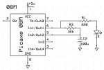
One possibility would be to use IO2's Schmitt Trigger feature to build a slow-speed oscillator. See the attached schematic:

When output 1 is high it charges the capacitor, until the voltage reaches pin 2's switching threshold. Output 1 is then set low and discharges the capacitor until it reaches pin 2's lower threshold (Schmitt trigger means the pin has hysteresis, i.e. once it switched high you have to go lower than the original threshold by a significant amount before it will switch back to low; similar for low-to-high transition. On the 08M the thresholds are approx. 1V and 4V for 5V supply).

With the given values (10 kOhm and 100 uF) the LED blinks approx. once per second.

Below is the code to test the concept:

Code:
myloop:

    if pin2 = 1 then
        low 1
    else
        high 1
    endif
        
goto myloop
Once that works you can modify the program to use an interrupt on pin2 instead of constantly querying its state - that way you can operate the output 1 toggles in the background while the main program is running.

Wolfgang
 

Attachments

Tyro

Member
Eclectic, I am powering the micro and sensing circuit with two AAA batteries. It is only switched on every sleep1 period, senses, calculates, etc., in about 10ms then goes back to sleep. The RF transmitter is powered from a 9volt battery which has normally no drain at all. After an alarm condition all the batteries are replaced.

Womai, Nice idea, I'll keep that, but now I am happy with my flickering LED, no extra parts required.
 

womai

Senior Member
Here's the code where I am using an interrupt to handle the blinking. The main program is now free to do whatever it wants.

Wolfgang

Code:
' ---------------------------------------------------------
' initial conditions

setint %00000100,%00000100 ' interrupt on pin2 high
high 1 ' start charging

' ---------------------------------------------------------
' main program

myloop:

    ' do whatever you want here
        
goto myloop

' ---------------------------------------------------------
' interrupt to handle LED blinking

interrupt:

    if pin1 = 1 then
        low 1 ' start discharging
        setint %00000000,%00000100 ' interrupt on pin2 low
    else
        high 1 ' start charging
        setint %00000100,%00000100 ' interrupt on pin2 high
    endif

return
 

sages

Member
just to throw a spanner in the works, processors/code can fail into a state where interrupts are still processed but the main code loop has crashed.
back in the days when i did a lot of embedded systems the watchdog/activity led code was allways in the main code loop. never in the interrupt code.
i know the opposite could occur, interrupts disabled and main code loop still operating, but there are ways around that.
the point of not using interrupts for watchdog/activity leds is that an interrupt is a hardware function that has a much higher degree of reliability than human generated code ;)

this consideration into where you perform certain functionality, and the fact that you are relying on an interpretor inside the picaxe, may be over the top for this application. something to ponder.
 

womai

Senior Member
sages,

that are interesting thoughts. Although in the case of the Picaxe - at least as far as I understand it - the interrupts aren't true hardware interrupts, but rather "polled interrupts", i.e. the Basic interpreter (which is running in the main loop) is manually checking the pin states after each command and if necessary jumps to another piece of Basic code to interpret (so still running in the main loop).

Wolfgang
 

hippy

Ex-Staff (retired)
@ womai : That's correct. Even for PICAXE with HINTx pins which flag a rising/falling edge instantly do not generate a call to the 'interrupt:' routine until the firmware checks (polls) to see if there are any interrupt triggers. These are 'deferred hardware interrupts'.
 

sages

Member
@ womai : That's correct. Even for PICAXE with HINTx pins which flag a rising/falling edge instantly do not generate a call to the 'interrupt:' routine until the firmware checks (polls) to see if there are any interrupt triggers. These are 'deferred hardware interrupts'.
phew, i'm not to old to learn something :)
forget my comment for picaxe, just remember it for systems with real hardware interrupts.
 
Top