How best to breadboard...

Dippy

Moderator
The MRF24J modules use a similar 'poor mans SMD' method.
I soldered them to some Harwin 0.1" pin headers and cut off the excess.
This makes a kind of DIP device.

The trouble with these is the pitch for 0.1" breadboard.

So, you may have to do a little bending or soldering on some wires.
Personally I would make a PCB breadboard so that there is no excess or bending things.
A pain, but it's 'nearer' to your final PCB design and PCB layout can affect RF designs.
 

clockwork

Member
Hi John

I had a look at these modules but like you I am not sure how to mount them to a breadboard and single sided PCB. I am not sure that the contacts are spaced a tenth of an inch apart but if they are some form of mount using pins and Veroboard might work.

Failing that I presume there is a IC holder available to house them, no doubt doubling the cost of using them.

I would also like to see some information on exactly how they can be connected to Picaxe type circuits and also how they could be driven with Picaxe type software.

Lets see what the experts can suggest.
 

clockwork

Member
I have just read through the Info on the Maplin Website re these modules.

It appears that there is a "Signal strength indication output - both analogue and digital.
I wonder if that means you could construct a "Field strength meter" for the receivers frequency failry easily. This could take the guesswork out of comparing aerials and so on.

This could be a useful project.
 

John O

Senior Member
Dippy: "The MRF24J modules use a similar 'poor mans SMD' method."

The HP03 pressure module (which I damaged soldering) also uses these half-round cut-outs. It certainly looks as though they'd fit into some sort of sprung socket (being through-half-hole-plated!).

eclectic: "Until you get a better answer, consider a couple of these and a hacksaw?

The problem is they're 2mm spacing instead of 2.54 - The XBee breakout board looks like the board and the module are 0.1"

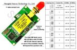
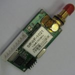
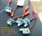
clockwork: Although I take it with a large pinch of salt, the datasheet claims upto 300m range so they're certainly worth looking into, I think. I've been in touch with Maplin and they're unable to supply any sort of adapter or breakout board.

As I'd seen the half-hole plated through connections before on the HP03 pressure module (albeit only 1mm spacing), I was wondering how they're actually mounted in a commercial item and whether it's replicatable for those of us who lack six-million-dollar-man eyeballs.

It does look like the home made PCB and veropins or similar might be the answer - thanks :) Individual pins from a normal header would probably be getting in each other's way.

John.
 

Dippy

Moderator
Make your own breakout board. SM them onto PCB and put a couple of lines of 0.1" for breadboard.

You'll enjoy the code writing. I did a pile of code for a CC1101 module. Same principle but a lot more of it. Have fun.
 

Dippy

Moderator
I think they only have one photo for the 'headline'.
Check the actual Data Sheets.
Or phone John Fairall at RF Solutions / Quasar.
Get the true info from the horse's mouth.
He's a jolly nice chap.

HopeRF comes from Stan's favourite place.
Alpha, I was told , come from Europe. true/false? I dunno.
 

srnet

Senior Member
Mount them on a 0.6" wide turned pin DIL socket, cut to length.

Solder fine wires to each of the module pins, projecting about 1cm below the module.

Form the wires to shape by pushing them through a bit of 0.1" stripboard.

Cut the now formed wires to the same depth and gently push into place into the holes on the turned pin socket. Put a bit of foam under the module to support it. Solder each wire in place.

You now have a RF module mounted on a DIL socket which you can plug direct into a breadboard or into another socket on a bit of stripboard.
 

manuka

Senior Member
These Alpha's indeed seem to be one of the numerous modules offered by HopeRF (with their RFM22 now considered superior) & US firm Sparkfun offer them as the RFM12(B). I recall a breakout board is available, but it costs as much as the modules!

Although cheap they may cause mucho hand wringing & head banging with the SPI setup, & the receiver sensitivity is only modest too. Of course the high data rates are pretty incidental for PICAXE use...

FWIW, for decent 433 MHz work (rather than simple "look ma- it works!" links that naturally have their place educationally),I've personally got to the stage where the cost is secondary to having GFSK modulation, buffering/error handling,10-25 mW TX power & higher RX sensitivity. Modules abound in the US$20 range that are powerful (but legal),very sensitive and far more user friendly. The jumper config'd Sunray transceivers recently mentioned by Grogster are typical,AND they come with a decent antenna & gold plated connector!
Stan.
 

Attachments

Last edited:

Dippy

Moderator
Amen to that.
Many people see a cheap little module and get over-excited... only to discover the amount of coding required to really get the most out of it.

I suspect that world-wide there are thousands of modules gathering dust in the backs of drawers.

But, if the coder is keen and competent then the experience may be worthwhile.


My only extra comment is that, in addition to Stan's criteria above , I would add "quality" and "quality control" generally.
I know "quality" is a swear word around here as it adds cost, but ANYONE here who has worked with the nitty-gritty RF chips and PCB design will realise that modules DO NEED calibration to get their frequencies spot-on.
CC1101 et cetera and MRF49s etc. do actually require setting up.
They will NOT be bang-on straight out of the box.
A low-cost manufacturer may not include that step in order to minimise cost. Result; 80% good, maybe not quite legal, but cheap so it keeps you boys happy.
I think "quality" is above GFSK in my list.

And QUALITY should be in all your lists.
If you pee your neighbour off you may get a visit. In most cases you get what you pay for.
 
Last edited:

srnet

Senior Member
Here is a RFM42 mounted on a DIL socket.

I would agree with the difficulty of setup of these Hope RF modules.

However in terms of facitilites and functions, I have yet to find a module that compares, at this physical size.
 

Attachments

manuka

Senior Member
Srnet: Well done- indeed a clever DIY breakout board! I've heard these HopeRF can even be persuaded to send audio,suiting lost RC model plane or balloon beacon use etc (see attached pix).

Dippy: That's surely only a good days work for a man of your calibre-city bankers would sniff at the sum...
 

Attachments

Last edited:

srnet

Senior Member
Srnet: Well done- indeed a clever DIY breakout board! I've heard these HopeRF can even be persuaded to send audio,suiting lost RC model plane or balloon beacon use etc (see attached pix).
Indeed they can, I have a working prototype lost model finder on a PCB being driven by a 28x2. Working out how to setup the RF module to transmit at all was not straight forward at all.
 

srnet

Senior Member
If you pee your neighbour off you may get a visit. In most cases you get what you pay for.
They are not for the average tinkerer thats for sure. Easy to get the frequency wrong, the deviation wrong, the power wrong (or leave the TX on all the time) and hence cause others problems.

The Hope modules I have tested so far (3 off) seem to be within about 5khz when setup for 434.100Mhz. My scanner says about 434.107Mhz and my frequency counter 434.103Mhz. Thats at circa 18C, I have yet to test the effect of putting the module in a freezer or heating them up. What would be real nice is to find someone local with a really accurate (calibrated) frequency referance, to check out the counter, I used to work for a company that had such things (AB Electronics) but no longer.

£5K is a bit much for me, get the price down to £10 and you might attract some custom.
 
Top