Jeremy Harris
Senior Member
I've tried searching the forum and can't find a mention of this, so before I go delving into trying to decode the bit stream sequence that these units use I thought I'd ask here first.
A bit of background:
There are quite a few RF encoded power switch/dimmer devices on the market. All seem to use 433MHz RF links, with at least a couple of encoding methods. I have an application where I need to switch a dozen or so low voltage circuits remotely and the HomeEasy range of switch transmitters seem ideal for the job (see here: http://www.homeeasy.eu/Transmitters/). I've purchased an HE308 dual wall switch transmitter to play around with and can get a bit stream out of a 433MHz receiver OK. The unit sends a repeating sequence that looks like this when a switch is made:
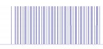
Each high pulse in the above bit sequence is about 280 to 290µS long, the short "zero" gaps are about 230µS, the long "zero" gaps are about 1.24mS and the initial very long "zero" gap is about 2.6mS long (I think this is probably the "start of data" marker). The time between repeated data bursts seems to be 10mS and the whole data burst seems to be about 69.42mS long.
My aim is to make a receiver that can output a simple serial code that corresponds to each switch and its condition, whenever a switch is pressed. I'll then feed that serial data into another Picaxe that can control 12V power switches on or off, as required (or even maybe PWM dim some of them). The ultimate aim is to be able to control LED lighting in a house, without needing to run 12V wiring to light switches. Each bank of 12V LED lights will be radially wired from the main control box, which may be some distance from the 433MHz receiver, hence the serial data link.
Try as I might I can't seem to find much out about the way these units encode data, so I'm going to have to try a brute force method to look at the pulse widths of the incoming stream and try and reverse engineer the format. Before I do this, I thought it worth asking here if anyone has tried something similar. If so some pointers as to any pitfalls found would be useful.
A bit of background:
There are quite a few RF encoded power switch/dimmer devices on the market. All seem to use 433MHz RF links, with at least a couple of encoding methods. I have an application where I need to switch a dozen or so low voltage circuits remotely and the HomeEasy range of switch transmitters seem ideal for the job (see here: http://www.homeeasy.eu/Transmitters/). I've purchased an HE308 dual wall switch transmitter to play around with and can get a bit stream out of a 433MHz receiver OK. The unit sends a repeating sequence that looks like this when a switch is made:
Each high pulse in the above bit sequence is about 280 to 290µS long, the short "zero" gaps are about 230µS, the long "zero" gaps are about 1.24mS and the initial very long "zero" gap is about 2.6mS long (I think this is probably the "start of data" marker). The time between repeated data bursts seems to be 10mS and the whole data burst seems to be about 69.42mS long.
My aim is to make a receiver that can output a simple serial code that corresponds to each switch and its condition, whenever a switch is pressed. I'll then feed that serial data into another Picaxe that can control 12V power switches on or off, as required (or even maybe PWM dim some of them). The ultimate aim is to be able to control LED lighting in a house, without needing to run 12V wiring to light switches. Each bank of 12V LED lights will be radially wired from the main control box, which may be some distance from the 433MHz receiver, hence the serial data link.
Try as I might I can't seem to find much out about the way these units encode data, so I'm going to have to try a brute force method to look at the pulse widths of the incoming stream and try and reverse engineer the format. Before I do this, I thought it worth asking here if anyone has tried something similar. If so some pointers as to any pitfalls found would be useful.