HELP

rbond9

New Member
Help,

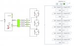
I am trying to produce an 08M driven Thermometer, I have multiplexed 6 LEDs from the 4 outputs (which took me all day).

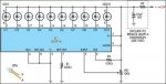
I have a circuit (not finished by the way) and have tested the outputs to give me the required signal to light 6 LEDs. Great!

However, I have used output pins 0,1,2 and 4 and am left with Input 3, this is not an ADC pin and can not be used as an output (not using my software anyway).

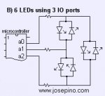
Any suggestions for a solution? One would be to multiplex the 6 LEDs from 3 outputs and use input 1,2 or 4 as the ADC input for the thermistor.

If anyone has the solution then please sketch out the circuit and especially the programme as it is driving up the wall.

Rich
 

Attachments

hippy

Ex-Staff (retired)
One possibility would be to use a second 08M which reads the thermometer on one of its ADC pins, sends that as serial data using SEROUT through an output pin which is read using SERIN on the unused Input Pin 3.

It may be easier considering upgrading to a 14M or 20M which has more I/O lines and will greatly simplify your circuit and software control.
 

Dippy

Moderator
Or maybe a shift register or 3-8 line decoder?
Sorry, haven't got a spare hour to draw schematic and write code ;)
 

MPep

Senior Member
What are you using for a temperature sensor? Would a DS18B20 not work here?
 
Last edited:

manuka

Senior Member
A DS18B20 would certainly be superior, but it currently seems to use (via the first diagram) a thermistor. But why 6 LEDs? Why not 4,7 ( 7 seg?) or 10 ? Temp. range covered? Of course for more outputs the 14M & 20M PICAXEs offer a quick fix- they're much the same price as a 08M.

Have you considered an LED bar graph with LM3914 driver IC? These DIP18 classics can be run in both bar & dot mode- the later being easier on the battery supply. In fact you may not -gasp!- even need a PICAXE if a LM3914 is used!

Thought (recalling a 555 version I used to run in the '90s) -maybe a single PICAXE driven LED that flashes increasingly rapidly as temp increases? These are at a glance "readable" from quite some distance away, & also have lower battery drain.
 

Attachments

Last edited:

SilentScreamer

Senior Member
Unfortunately that uses a technique called "charlieplexing". That can be done with a PICAXE but not using an 08M using Output Pin 0 as that is output only.
I think you could use it to get 6 LEDs out of 08M using outputs 0, 1 and 2, I'll happily draw the circuit diagram if someone else can confirm that its possible first?
 

vttom

Senior Member
Actually, you can still use one of the bi-directional pins as an ADC input AND as an output to drive an LED.

In your program, set the direction to make it an input, take the ADC reading, then make it an output and drive whatever combination of LEDs you want to drive. Pause for some amount of time (can't imagine you'd need to read it more frequently than once per second), then repeat ad infinitum.

The time spent reading the ADC will be so short relative to the amount of time you spend driving the LEDs, you'll never notice it.
 

BCJKiwi

Senior Member
@vttom

Could be an issue with the 'shared' use of ADC and LED on the same pin as it appears the LEDS will be charlieplexed which typically requires the pin to be both an output high and outpu low as well as input (tristate). Not sure how READADC read would co-exist with this arrangement.
 
Bi/Tri colour leds

If you don't need a bar type display you could use bi/tri colour leds. Use colour as the scale. I guess thats a bit like what you have, you do get more leds.

The price of the leds is the bad part. With the added expense you may as well go for a bigger chip.
 

rbond9

New Member
So I guess that it can't be done with an 08M. I'm not messing around with devices like the DS18B20.

Going to a 14M would increase the cost by 41 pence and push me over budget as I get the 08M chips at £1.29 each (I buy 225 at a time with the pre drilled PCB's).

I will hold on for more input from you guys before scrapping the idea completely. Thanks for the info so far.
 

eclectic

Moderator
So I guess that it can't be done with an 08M. I'm not messing around with devices like the DS18B20.

Going to a 14M would increase the cost by 41 pence and push me over budget as I get the 08M chips at £1.29 each (I buy 225 at a time with the pre drilled PCB's).

I will hold on for more input from you guys before scrapping the idea completely. Thanks for the info so far.
Could you provide an outline of your

"Thermometer"requirements?

At the moment, it appears to be six "bars".

Could it be achieved with three?

Red / Amber / Green LED?

e
 

inglewoodpete

Senior Member
I have successfully used a bothway pin on an 08M to read ADC and drive a LED when it's not an input. There are two catches: the ADC input must be limited to < 0.6v (reverse-biassed LED breakdown voltage) and both outputs associated with the LEDS connected to that pin must be set to Low (better still, inputs).

Experiment!
 

rbond9

New Member
Could you provide an outline of your
"Thermometer"requirements?
At the moment, it appears to be six "bars".
Could it be achieved with three?
Red / Amber / Green LED?
e
I am basically trying to rip off this project:
http://www.kitronik.co.uk/thermkit.htm

My budget is £2 per student as I have 220 students in each year group. I am looking at year 8 (12-13 year olds) only for this project. We currently buy another project http://www.kitronik.co.uk/ampkit.htm from this firm for year 9 but they are cheaper (non-pic) and they can negociate a little on large orders.

The kit in question has 8 LED's and I compromised at 6. The sensor is a simple thermistor-resistor potential divider arrangement. I am not bothered about the two temperature ranges (indoor and outdoor) or the on-demand sensor reading.

I hope this is clearer than before.
 

sleazyd

New Member
I'm with Dippy, serial shift out is the easiest and probably simplest solution. You can use 3 output pins as clock, data, and enable so you can change brightness, or an output strobe. A 74l595 (74HC595, etc) is under a buck in the US, and with some clever wiring (wire -OE and ST_CP together) you can get it to run 8 outputs from 3 wires.
 

rbond9

New Member
:confused: I'm confused now, serial shift? WTF!

I might have to compromise a little more and try to get 5 LED's from 3 outputs, I have not tried yet but I am pretty sure it is doable which then gives me 2 inputs, one of which would be an ADC for my thermistor potential divider and a spare digital input for sommat else. It's getting late and I'm tired! :rolleyes:

Rich
 

vttom

Senior Member
I just had a thought. Consider this circuit...

Code:
            R      
        +--/\/\/--+ V3
        |         |
        |        -+-
        |        \ /
        |         V
        |        ---
        |   R     |
Vin o---+--/\/\/--+ V2
        |         |
        |        -+-
        +        \ /
        |         V
        |        ---
        |   R     |
        +--/\/\/--+ V1
                  |
                 -+-
                 \ /
                  V
                 ---
                  |
                  |
                -----
                 ---
                  -
When Vin = 0, V1=V2=V3=0.

When Vin > Vthresh, the bottom diode will turn on and V1=Vthresh.

When Vin > 2 x Vthresh, the bottom 2 diodes will turn on and V1=Vthresh and V2 = 2 x Vthresh.

When Vin > 3 x Vthresh, all three diodes will turn on and V1 = Vthresh, V2 = 2 x Vthresh, and V3 = 3 x Vthresh.


It is not uncommon to generate a (more or less) DC voltage from a single output pin using PWM. So... you might be able to do what you want using a single output pin and VDD/Vthresh LEDs.
 
Last edited:
Top