help !

sid

Senior Member
I used a digital camera > Put image on PC > Edited image for size and framing > Uploaded it to a host (in this case my own webspace provided free by my ISP) > Copied the URL of the image > Embedded the image into my post by using the IMG tags thus: {img}http://image_url.jpg{/img}

(Note you must replace '{' with '[', and replace '}' with ']'. If I had typed it that way, the forum would think I am trying to post an image)

Once you know the URL of an image anyplace on the net, you can embed it in your post with the IMG tags.

If you right-click my image above > Select properties. You can see the URL of the image. Same with any image on any webpage.
Hi Boriz,
I've dicovered another way of uploading pic's
1 take photo
2 download onto pc
3 right click on photo and click on send to mail recipent
4 choose the option to make photos smaller
5 email to your self
6 from sent items right click and save photos now much reduced in size
7 use the manage attachment options as discribed by eclectic to attach photos
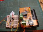
 

sid

Senior Member
Hi Dr acula & Boriz,
Lots of techy info there from both of you which I confess to not understanding all that you say, but while playing around last night I discovered that by connecting the output of the ir sensor directly into the input of the picaxe ......it works! :)(see attached pics)
And it even works when ir is bounced off an object and back into the sensor up to about an inch away which is perfect , however :confused:.... it only works in poor light conditions, when used in either daylight or a brightly lit room the sensor acts like it's seen ir (which I guess exisits in most forms of light) and goes high/
Any ideas on how to tame the sensor ?
Incidently the emittor and sensor are both from rapid electronics.com and the can be viewed at the following address
http://www.rapidonline.com/productinfo.aspx?tier1URL=Electronic-Components&tier2URL=Optoelectronics&tier3URL=Infrared-Devices&tier4URL=3mm-Infrared-source-and-sensor&moduleno=29397#techspec
Everybobys help with this project really is appreciated,
Cheers, Sid
almost working ir1.jpg

almost working ir2.jpg
 

moxhamj

New Member
Think of IR light as red light. It is only just out of the visible range. So if you have any lights on, they will swamp the receiver. You can partially solve the problem with little brass tubes pointing at each other so they only 'see' each other. If you only want to go across a railway track it should work fine.
 

boriz

Senior Member
Ambient light effecting IR sensors is a common problem. Here’s a couple of common solutions:

Place the sensors so that the IR receiver is not exposed to more than a minimum amount of ambient light.

Use an optical filter over the IR receiver to block out all but IR light. You can find stuff like this from various electronic shops, but you can also brew your own: Find an old photograph wallet (the type you used to get from the developers) and examine the negatives. At the end of the reel there should be a few inches of ‘black’ film which has been processed but contains no image. This functions as an IR pass filter. So does a slice of the brown floppy magnetic material used in a 3.5” floppy disk.

Modulate. This is a little trickier, but serves well for TV remotes and such. It just means that the IR TX is switched on and off with a predictable pattern and the RX rejects everything except this pattern.

P.S. Nice 'out of the box' thinking on the image resizing. But there are much better ways.
 

sid

Senior Member
Thanks Boriz,
I tried your idea with the film strip and your spot on,it works:).
I then went one further and replaced the ir sensor with a phototransistor that has a built in daylight filter and a BC548 which works well as there is no need for shrouding either of the leds :D
ir filter+transistor1.jpg

ir filter+transistor2.jpg
But it still sees tungstan lighting and false triggers, so your modulation idea looks like it might be the answer.
I think I understand the theroy in that, I write some code that flashs the ir emittor on and off eg:50 times a second and then I write some more code that recognises that an input is "modulating" and use that as the input to goto the next part of the program. By doing this the pixace ignores all input from the phototransistor unless it matchs the flashing rate of the emitter.
While I think that's what you mean, and I could write the code required to flash the ir emitter on/off, I have no idea how to write the required code to make the picaxe recognise the modulation.
I would be as ever grateful for any advise or code you could post that I could play around with.
Rgds,
Sid
 

westaust55

Moderator
Infrared Detectors

Would an IR receiver comprising the IR detector, amplifier, modulator etc be useful for your applications?
Jaycar sell such an items:
http://www.jaycar.com.au/products_uploaded/ZD-1952.pdf

I have also seen the same type of receivers down to 30kHz. Assumption being the lower frequency will be easier for a PICAXE to generate at the transmitting IR diode. Maybe with PWM as the 08 does have one PWM output.
 

boriz

Senior Member
Like I said, modulating is trickier. Mainly because you might need two AXEs. One as the TX modulator and the other as the RX demodulator/detector. But I can think of at least one way you might be able to do it with a single AXE:

(psudo-code)
Set TX output high (illuminating the IR LED)
Pause 1ms
Check RX input from sensor = high
Set TX output low (extinguishing IR LED)
Pause 1ms
Check RX input from sensor = low
Repeat…

If your RX pattern matches your TX pattern then you have line-of-sight. Otherwise you don’t. Bear in mind that artificial lighting flickers at mains frequencies, so try to make your timing significantly different from the line frequency.

If you don’t mind using two AXEs then it’s even simpler because of the built-in IR TX/RX commands. You will need a receiver device like this which contains it’s own amplification and demodulation circuitry. See AXE manual command reference for INFRAIN.

Just have one AXE constantly send a single code and the RX check to see if it is receiving that same code. Range can be improved by using more powerful LEDs and/or VERY short pulses of high current.
 

sid

Senior Member
Thanks,
Because I intend to use the leds side by side under the track so a passing train will reflect the ir from the emitter back into reciever I think I'll try and use your first suggestion as the sensor you suggest using in the second is not really practical for the device I'm trying to create.
This might take me some time while I'm learning code
Cheers, Sid
 

sid

Senior Member
Thanks for the advice but because of the reasons exlained in my last post I'm going to try and see if I can get the ir emitter to flash on/off and get an input to recognise the flash rate, any suggestions re code would be welcome.
Cheers, Sid
 

sid

Senior Member
I've finally found a solution to my ambiant light problem

Hey Boriz, much thanks for all your help.
Because I model in n gauge (2mm=1') I'm determinded to keep to the 2 pin 3mm leds that I've chosen, I am also determind to place them "under" the track as opposed to beside the track and because of this, even using the pulse technique, if the sensor is already flooded with ir from daylight or tungsatn I'm assuming it won't recognise the pulsed input as it will already be fully on

However I've done a bit of side ways thinking and come up with a solution :).
At startup if the ir emittor is off and the sensor is on then it must be ir from daylight/tungstan so set the program to go to a daylight routine which thinks that a train has past over head when the sensor goes low (no ir) signal to red, keep checking sensor, when it goes high (trains passed) run the red ,yellow, green sequence.
If at start up the the ir emittor is off and the sensor is low then it must night so the program then defaults to a night time routine and switch's the ir emittor on, when the sensor goes high it's because a train has passed overhead and bounced the emitter ir back into the sensor, when the sensor goes low again it's because the train has passed and has stopped reflecting ir and so the r,y,g sequence can begin.

I've modified my circuit so the ir emitter is now connected to 0v via outout4
I've written some code and it actually works !:D
The program still needs a few tweaks but in effect I've used the light level on startup as a kind of flip/flop switch.
If there is light then act when the sensor is low
If there is no light then act when the sensor is high
Obvious really

Once again thanks for everyones input, I wouldn't have got to this point without your help
Cheers,
Sid
 

boriz

Senior Member
The idea behind modulation is that ambient light, no matter how bright, does not oscillate at your chosen frequency. Yes the IR sensor may become swamped, but that just means that it’s gain/operating point needs to change a little. This is usually achieved automatically with some sort of feedback.

If you dismantle the IR receiver circuit on an old enough TV, you will find it has a normal/basic IR phototransistor (such as the one you are using), plus some discrete circuitry that works a little bit like a radio receiver in that it employs a ‘tuned’ circuit to amplify the incoming AC signals. Because it’s tuned, the amplification is different for different frequencies. Specifically it’s gain is very large for the IR remote’s frequency (38Khz?), but drops off sharply to zero for any AC signals of higher or lower frequency, also rejecting DC.

The more modern ‘complete IR receiver circuit in one 3-pin package’ works in exactly the same way.

As has been suggested, using various beam shading / filtering techniques, you can improve rejection significantly, but the real rejection power comes from modulation. Just look at how well TV remotes work in all manner of ambient lighting conditions.

Still. Whatever works!
 

sid

Senior Member
Like I said, modulating is trickier. Mainly because you might need two AXEs. One as the TX modulator and the other as the RX demodulator/detector. But I can think of at least one way you might be able to do it with a single AXE:

(psudo-code)
Set TX output high (illuminating the IR LED)
Pause 1ms
Check RX input from sensor = high
Set TX output low (extinguishing IR LED)
Pause 1ms
Check RX input from sensor = low
Repeat…

If your RX pattern matches your TX pattern then you have line-of-sight. Otherwise you don’t. Bear in mind that artificial lighting flickers at mains frequencies, so try to make your timing significantly different from the line frequency.

If you don’t mind using two AXEs then it’s even simpler because of the built-in IR TX/RX commands. You will need a receiver device like this which contains it’s own amplification and demodulation circuitry. See AXE manual command reference for INFRAIN.

Just have one AXE constantly send a single code and the RX check to see if it is receiving that same code. Range can be improved by using more powerful LEDs and/or VERY short pulses of high current.
Hi Boriz,
Even though I've got my project to work well enough for my needs, I'm still interested in the other solutions suggested.
Following your advice above Ive written the following code...
symbol tx = 1
symbol rx = 2
symbol led = 0
symbol counter = b0
counter = 0

main:
counter = 0
high tx
pause 1
if input2 = output1 then goto nextcheck
goto main
nextcheck:
low tx
pause 1
if input2 = output1 then flash
goto main

flash:
counter = counter + 1
if counter = 5 then goto main
high led
pause 250
low led
goto flash


It seems to work well enough in the simulator but...only when the input is a higher numbered pin than the output pin :confused:
If you cut and paste this code into the simulator and then swap the pins around so the tx is pin2 and the rx is pin1 it doesn't work.
Is there a reason for this ?.
 

westaust55

Moderator
I think if relates to the line :

Code:
if input2 = output1 then goto nextcheck
where 2 is still the input and 1 is still the output

this modified version has swapped Tx and Rx:

Code:
symbol tx = 2
symbol rx = 1
symbol led = 0
symbol counter = b0 
counter = 0

main:
counter = 0 
high tx
pause 1
if pin1 = 0 then goto main

low tx
hold:
pause 1
if pin1 = 1 then goto hold
 
flash:
counter = counter + 1
if counter = 5 then goto main
high led
pause 250
low led
goto flash
 

sid

Senior Member
I must be really dim not to get this, but here is the code with the output pin on a higher numbered pin than the input pin
symbol tx = 2 'output on pin2
symbol rx = 1 'input on pin1
symbol led = 0
symbol counter = b0
counter = 0

main:
counter = 0
high tx
pause 1
if input1 = output2 then goto nextcheck ' if pin1=pin2
goto main
nextcheck:
low tx
pause 1
if input1 = output2 then flash 'if pin1=pin2
goto main

flash:
counter = counter + 1
if counter = 5 then goto main
high led
pause 250
low led
goto flash
If you cut and paste that into the simulator it won't work but change the 1 and the 2 around for both the tx/rx and input/output so that the input is on a higher numbered pin and then it does?
What am I not seeing ?
 

westaust55

Moderator
I can see what you are trying to achieve but you are not using correct programming statements according to the PICAXE manual 2.

Input and Output commands are used on the PICAXE 08/08M to set IO direction as inputs or outputs.
For this purpose there is a space between the command and the number of the pin to be changed.

The terms such as ”input1” and “output2” are reserved words in the PE but not defined as to their meaning. Maybe for the forthcoming X2?

When using inputs the input variable names (pin1, pin2 etc) must be used

Did you look at the code I posted for you ?
That code is using the term “pin” as opposed to “input” in the IF…THEN statement.
 

hippy

Ex-Staff (retired)
The terms such as ”input1” and “output2” are reserved words in the PE but not defined as to their meaning. Maybe for the forthcoming X2?
That's what the root of this problem is.

OUTPUT0 through OUTPUT7 are numeric constants 0 through 7, INPUT0 through INPUT7 are synonyms for PIN0 through PIN7.

The statement "IF input1 = output2 THEN" is therefore, "IF pin1 = 2 THEN", which will never be true, pin1 can only ever have value 0 or 1.

When changed to "IF input2 = output1 THEN" it becomes "IF pin2 = 1 THEN", which does make more sense, but I doubt either are doing what is actually intended. I'm not however entirely sure what is intended.

If the intent is to respond when an input pin matches an output pin then, "IF pinX = outpinY THEN" could be presumed as what's required, but in this case ( and with "LET b0=outpinY" ), the "outpinY" is a synonym of "pinY", an input pin.

All very confusing; "pin1", "input1" and "outpin1" all refer to the same thing when on the right of an assignment or used within an IF/DO-LOOP conditional. Consider this -

LET input1 = outpin2

What that does is set output pin1 to the value of input pin 2 :)
 
Last edited:

sid

Senior Member
Thanks Hippy, (and thanks Westaust55)
I followed your post as far as paragraph 3 (or should that be paragraph3) and then I lost the plot.
However I do understand IF pin 2 = 1 THEN.... or IF pin 2 = 0 THEN... that does make sense.
To be honest I'm just playing around now, trying some of the suggestions made earlier in the posts.
The idea is to use a HIGH/LOW instruction to pulse an ir led and then look for that pulse on an input pin from a phototransistor, so when the input matchs the output THEN GOTO etc. (without having to use the pwm instruction as I don't want to use the 3pin ir sensor).
 

BeanieBots

Moderator
Ah, not with the same PICAXE you won't.
When you pulse the LED, the program is pulsing, when you read the input, the pulsing has finished, so you will NEVER see the pulse unless you use a second PICAXE.

That's a bit like popping into your bedroom, turning the light on and off, then popping outside to see if you can see the flash. You can't be in two places at the same time.

PWMout is a background task.
High/low are sequencial commands.
 
Last edited:

westaust55

Moderator
One option may be to use an external one-shot such as a 74HC221 to create a pulse stretcher.

Untested but a short pulse could be extended from say 1 to a few milli seconds to give the same PICAXE time to see the signal.
 

boriz

Senior Member
My suggestion (Which I might point out, I have never tried), was intended as one possible method whereby a single PICAXE could perform a kind of modulation and detection.

It’s simply a matter of lighting the LED, seeing if the input from the sensor is high, then extinguishing the LED and seeing if the input from the sensor is low. After repeating this a few times, if the input pattern matches the output pattern, then you must have line of sight. It’s not quite true modulation, but better than none at all I suspect.

The pause is in there to allow the sensor to stabilise. It will be working with low current and will probably need a little time to charge it’s own junction capacitance. But that’s just a guess and it might work just as well without.

Does the INFRAIN2 command stop the background PWM oscillator?
 

hippy

Ex-Staff (retired)
Does the INFRAIN2 command stop the background PWM oscillator?

Probably not but as INFRAIN/2 expects a modulated signal I'm not sure how you'd modulate the PWM at the same time. To detect the PWM carrier you can simply use the TSOP IR receiver output ( active low ).
 

sid

Senior Member
My suggestion (Which I might point out, I have never tried), was intended as one possible method whereby a single PICAXE could perform a kind of modulation and detection.

It’s simply a matter of lighting the LED, seeing if the input from the sensor is high, then extinguishing the LED and seeing if the input from the sensor is low. After repeating this a few times, if the input pattern matches the output pattern, then you must have line of sight. It’s not quite true modulation, but better than none at all I suspect.

The pause is in there to allow the sensor to stabilise. It will be working with low current and will probably need a little time to charge it’s own junction capacitance. But that’s just a guess and it might work just as well without.

Does the INFRAIN2 command stop the background PWM oscillator?
That is exactly what I had in mind and when I've finished faffing around with my current project I'm going to knock up a breadboard and see if it will work, I see no reason why it won't.
 
Top