Help with voltage level converter, please.

John O

Senior Member
Hi All,

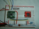
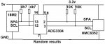
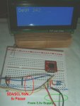
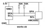
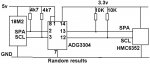
I'm playing with the HMC6532 pressure module. All works ok when I run both picaxe and the module at 3.3volts but, when I try to use a voltage level converter with the picaxe at 5v and the module at 3.3v, the results are very erratic. Someimes, it gives the correct reading but more often it gives either 1740 or 6553.

I've tried it with and without pull up resistors one one side and both sides with similar results. I've got two 0.1uF caps,. not shown on the drawings below.

Code:
; HMC6352 compass module


init:

  hsersetup B9600_4, %10000 				;Use LCD Pin 1, no hserin 

  hserout 0, (13) : pause 100           		;Initialize LCD
  hserout 0, (13) : pause 100
  hserout 0, (13) : pause 100
  pause 500
  hserout 0, ("ac1", 13)  				;Clear display
  pause 50                				
  hserout 0, ("acc", 13)                  	;Hide cursor


  i2cslave $42, i2cslow, i2cbyte 			;Set HMC6352 device address

main:

  i2cwrite ($41)						;'Get Data' command
  pause 50

  i2cread (b1,b0)						;Read in two bytes
   
  hserout 0, ("ac80", 13)				;Position LCD cursor
  hserout 0, ("adDeg: ", 13)
   
 
  w0 = w0 / 10
  
  hserout 0, ("ad", #w0, "   ", 13)

  pause 500
  goto main
Any suggestions would be appreciated!

edit: I've shown the voltages to the level converter the wrong way round on the drawing but I do have them the right way round..

3.3v to pins 1 and 8 and 5v to pin 14.


Thanks,

John.
 

Attachments

Last edited:

Janne

Senior Member
edit: I've shown the voltages to the level converter the wrong way round on the drawing but I do have them the right way round..

3.3v to pins 1 and 8 and 5v to pin 14.
Are the signals also on the correct side, ie. picaxe signals connected to pins 12 & 13, and HMC connected to 2 & 3 ?.

The datasheet also gives a hint, that the adg3304 is only capable of driving cmos inputs, so it might be worth trying a weaker pull-up on the i2c bus /and or slower bus speed. Also add decoupling the the adg3304 in case it is lacking it.
 

hippy

Technical Support
Staff member
Is the problem that this is a voltage level convertor not an open-collector I2C bus driver with each side operating at differing voltages ?

The datasheets mention SPI and Microwire ( a subset of SPI ) but not I2C; you'd have expected that mentioned for a wider market share if it could do it. Nothing immediately turned up on Google either.

It could perhaps work, but I haven't studied the datasheet.
 

John O

Senior Member
@ Janne: Yes, sorry, it was late in the day when I did the drawing. The correcred version is below. I've also attached the breadboard layout I'm using.

@ hippy: I'm not sure. Getting a bit deep for me :) The datasheet says "The ADG3304 level translator is designed to drive CMOS-compatible loads." and on page 18 there's a diagram connecting two Microcontrollers together.

http://docs-europe.electrocomponents.com/webdocs/0aa5/0900766b80aa5cbc.pdf

I'll have another play today :)

Thanks,

John.
 

Attachments

Last edited:

John O

Senior Member
Thanks for the links. I did find that informative link of yours this morning.. and the Philips application note.

It looks like, typically of me, I've tried to find an elegant solution to a trivial problem and ended up with a relatively expensive dog's dinner!

Both of our local suppliers of the 2N7000 have a minimum 20 UKP order so I'll wait until I need some other stuff. (Unless I've missed them in the Picaxe shop?)

Thanks again...

John.
 

eclectic

Moderator
Thanks for the links. I did find that informative link of yours this morning.. and the Philips application note.

It looks like, typically of me, I've tried to find an elegant solution to a trivial problem and ended up with a relatively expensive dog's dinner!

Both of our local suppliers of the 2N7000 have a minimum 20 UKP order so I'll wait until I need some other stuff. (Unless I've missed them in the Picaxe shop?)

Thanks again...

John.
John.
bottom of the page here:
http://www.bitsbox.co.uk/transistors.html

Westy
Jaycar ship from Oz, and takes ages to deliver.

e
 

hippy

Technical Support
Staff member
I've mentioned it a number of times before and haven't seen any argument it won't work but never had any feedback on it so I guess no one's tried it ...

With I2C properly configured, SDA and SCL will be open collector outputs on both PICAXE and I2C device, so a 5V PICAXE should interface to a 3V3 I2C device with no level conversion needed. The pull-ups should go to the lowest supply.

Untried by myself it is just a theory so it has to be tried entirely at your own risk but I believe it's a sound theory. The only risk is setting SDA or SCL high, and that's a risk no matter what the I2C device voltage is.
 
Last edited:

westaust55

Moderator
I've mentioned it a number of times before and haven't seen any argument it won't work but never had any feedback on it so I guess no one's tried it ...
If "it" is the use of an FET such as the 2N7000, as a bi-directional level shifter, I have done "it" several times on different project a year or so back and it works a dream - hence I keep making the suggestion.
 

John O

Senior Member
It took "it" to mean just conencting the two devices together - hard-wired with nothing between. But with the two pull-up resistors connected to the lower supply.

John.
 

hippy

Technical Support
Staff member
Yes "it" was meant to be "the following...", ie straight connection, pull-ups to lowest voltage, no level shifting.

I always prefer the simplest / cheapest solution that doesn't have any noted 'wont work' about it. As long as the voltage of SDA and SCL is high enough for both sides to read as logic high there shouldn't be any problem, as it's open-collector the input pin should never see a voltage greater than what the pull-up is tied to.

It should also be possible to interface a 3V3 PICAXE to 5V I2C device with simple passive components; an R and a diode in parallel ( cathode towards PICAXE ) - As long as the SDA and SCL are pulled low enough to be seen as logic low by the I2C device. The R current limits the 5V into the 3V3 PICAXE.
 

hippy

Technical Support
Staff member
It seems to work! Although the compass module is rated at 5.2v max so it may not be a fair trial!
The only proof is the test with real hardware but I'd say that's a fair proof of concept test as the I2C device is powered at 3V3. It's what I'd have done. I was contemplating finding another PSU and wiring up an I2C Eeprom the same way so that saves me that effort - thanks!

An improvement for robustness might be R's on SDA and SCL between pull-ups and the 3V3 I2C device to limit current should the PICAXE ever put out 5V. Not sure what values and might have to experiment there.
 

John O

Senior Member
I guess it may depend on the particular devices (?) but 8k2 worked but 10k didn't. I settled for 4k7 so it's not on the edge.


Code:
                              -------------------- 3v3
                              |
                             10k
                              |
(5v) SDA/SCL -----------------+------- 4k7 --------(3v device)

0v -------------------------------------------------0v

John.
 

MartinM57

Moderator
For safety (and subject to test, but you don't really want to do the test ;)) put 1k/2k resistors between your + sign and the 4 of 4k7 in your ASCII art - just in case you configure the SDA/SCL pins accidentally to output and set them to logic 1....potentially bad news for the 3v3 device...
 

hippy

Technical Support
Staff member
I guess it may depend on the particular devices (?) but 8k2 worked but 10k didn't. I settled for 4k7 so it's not on the edge.
Ideal value would depend on device and worse case, full 5V into the chip ( assuming that's pulling down to 0V ), R = V/I. where I is the max current the chip can sink. If it's 1mA that's 5K so 4K7 is a reasonable choice but could go lower if it can handle more, if 20mA can drop to 250R.

If the input is clamping to its 3V3, I = (5V-3V3)/R, for 4K7 that's below 1mA, for 250R it's 7mA. So if the chip can sink that it's fine.

Also it's protection against something not expected to happen. Considered as a safety net, rather than guaranteed protection, anything is hopefully better than nothing.
 

hippy

Technical Support
Staff member
So... increase the 4k7 to 6k8 ??

Don't know; what's the maximum current that the chip can sink via SDA / SCL ?

I'd guess most chips could withstand around 1mA but that is a guess, so 4K7 sounds "probably okay" to me, but you'd have to check datasheets. Going up above 6K8 may be better, maybe 4K7 is okay.

It is 'intuitive, finger in the air, design' rather than 'engineered design', but that's the choice, or somewhere in between. Do it properly and we'll be using I2C level converters. Do it cheapest and we'll have no current limiting and keep our fingers crossed.
 

John O

Senior Member
@MartinM57 - 6k8 seems to work ok so I'll leave it at that.

The specs don't seem to give the maximum current so the higher the resistor the better, I guess. I've got a bag of 2N7000's on their way anyway now so I'll be able to have a dabble with those as well :)

John.
 

hippy

Technical Support
Staff member
the higher the resistor the better, I guess

Yes, that's how I guess too :)

Try high, go lower if it doesn't work, choose somewhere below what doesn't work, hope it's good enough, hope its protection is not needed anyway.
 

papaof2

Senior Member
Ther is a chip made for 3v-5v I2C interfacing - the PCA 9515. I have a project using one with a digital compass and a PICAXE, but so far only in the design stage.

I'll probably get to the breadboard in a week or two.

John
 

John O

Senior Member
I ordered a few 2N7000 MOSFETs from BitsBox yesterday at just after 11am and the postie arrived with them this morning! Not bad going :)

Two installed and up and running!


John.
 
Last edited:
Top