Help with tachometer

lewisg

Senior Member
I'm attempting to put a tach on my lathe using a hall effect sensor. I should be getting an RPM range of 60 to 600 but I'm only getting 60 to 180. And the output is very intermittent and jumpy.

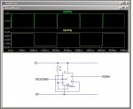
The pulses look good (to me...):HallEffect_FullSpeed.jpgHallEffect_HalfSpeed.jpg

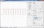
Here is the relevant part of the code:
Code:
count HallPin, 1000, RPMCount     'pulses in second
RPMCount = RPMCount * 60          'pulses in 1 minute
BinToASCII RPMCount,Dis10000,Dis1000,Dis100,Dis10,Dis1
serout LCDpin, t9600_8,(254,192,  "RPM:",Dis1000,Dis100,Dis10,Dis1)
I guess this could be done with PULSIN but I'm unsure of the math or if a Picaxe will measure the correct part of the waveform. With real numbers I'd do: RPM=60/(pulse/1000)...

Any ideas?
 

AllyCat

Senior Member
Hi,

Yes those pulses do look quite narrow, but because they're only one 'scope sample wide it's not easy to say whether the PICaxe will "see" them all or not.

But anyway, your code above is not going to give very good results. Suppose the lathe is running at 100rpm. Then sometimes the one second counting "window" will see one pulse, sometimes two. Thus the result can only oscillate in a random manner between 60 rpm and 120rpm.

With real numbers I'd do: RPM=60/(pulse/1000)...
Yes, you're on the right track there, just rearrange (and correct) to give:

RPM = 60,000 / Period of one revolution in milliseconds

60,000 conveniently just fits into a PICaxe "Word" variable of 16 bits (maximum is 65,535) so you just need to measure the period of one revolution in ms. If the "pulse" is very narrow then the width of the "space" inbetween may be adequate, but IMHO it's far better to do the job properly:

Unfortunately, a PICaxe cannot measure the complete period directly, but it can measure a "pulse" time, then immediately afterwards the "space" time, add them together and convert to milliseconds. ;)

Cheers, Alan.
 

Goeytex

Senior Member
If you want to try pulsin, the signal can be conditioned with a J-K flip flop (or other IC) as shown in the SPICE simulation below. The top signal is the output of the Hall Sensor and the bottom signal is the output of the Flip-Flop.

By conditioning the signal as shown, pulsin reads the actual time period (in pulsin units). The math to convert to RPM is simple and if you choose to use pulsin there are plenty of folks here that can help with the math.

The nice thing about using pulsin is that you don't have to count hundreds of pulses to get an accurate reading. It can be done in done in one shaft revolution.

The code will look something like below, depending upon what Picaxe you are using. In order to read low RPM the Picaxe MUST run at 4 Mhz or else pulsin will time out and return a zero value. This code is good down to 92 RPM.

Code:
[COLOR="#008000"]'**************************[/COLOR]
[COLOR="#008000"]'*  Low RPM Using Pulsin  * [/COLOR]   
[COLOR="#008000"]'**************************[/COLOR]

#Picaxe 08M2
#no_data
Setfreq M4    [COLOR="#008000"]'Just in case[/COLOR]
Pause 100

symbol Pulsin_Val =w0
symbol Period_ms = w1
symbol RPM = w2

Main: 
do

     pulsin c.4,1,Pulsin_Val
     period_ms = pulsin_val / 100  [COLOR="#008000"]'Convert to ms  [/COLOR]
     RPM = 60000 / period_ms       [COLOR="#008000"]'Calculate RPM[/COLOR]
     sertxd ("RPM = ",#RPM,cr,lf) 
     pause 500

loop
 

Attachments

Last edited:

lewisg

Senior Member
Thanks!

I'll look around for a flip flop and give it a try.

Currently I'm getting fairly good results from around 100 to 2200 RPM to with this:
Code:
pulsin HallPin, 0, RPMCount
RPMCount = 60000 / RPMCount
RPMCount = RPMCount * 10
I don't have a tach to verify but the 4 step pulley set on lathe is marked for a 1725 RPM motor. I'm measuring using a 1140 RPM motor with a VFD. The results I get are:
Code:
marked   measured
------   --------
 2300      2230
 1450      1370
  900       850
  430       400
Now I need to get SFM to behave within the limits of Picaxe...
 

Goeytex

Senior Member
The inaccuracy with the above code is because the short pulse also changes in duration and is not being read. You might be able to do two reads and then add the values together to get more accurate time period. Something like this.

Code:
symbol HallPin = c.3
symbol mark = w0 
symbol space = w1
symbol RPMCount = w2

DO
   pulsin HallPin, 1, Mark
   pulsin HallPin, 0, Space
   RPMCount = mark + space
   RPMCount = 60000 / RPMCount * 10 
   sertxd (#RPMCount,cr,lf)   

LOOP
 

boriz

Senior Member
You should be able to use the internal comparator as a pulse stretcher / conditioner. This app note might be useful. It's just given me and idea. Starting another thread.
 

lewisg

Senior Member
The inaccuracy with the above code is because the short pulse also changes in duration and is not being read. You might be able to do two reads and then add the values together to get more accurate time period.
For what I'm doing the accuracy is fine. The flip-flop circuit will likely help to make things more stable but for running a lathe + - 10% doesn't make much of a difference. Same with the SFM calculation. Even though the lathe has a 6" swing most of what I turn is less than 2" in diameter. Here is a good reference of cutting speeds. With this lathe the max that could ever happen is 6 * .2618 * 2230 = 3503. However you never cut at over 600 or so SFM so 999 would be a good practical max since I'm only displaying 3 digits.


What Picaxe are you using?
28X2 on a AXE401 board mated to a Seed Studio Motor Shield V1.2.

This project has two modes of operation. RPM/SFM and running a stepper motor that can move the lathe carriage. Since I like it when others post code I'll post where I am right now.

Code:
I would post the code but it puts me over the character limit. Dang!
I likely need to use AllyCat's div31 routine to solve the SFM problem...
 
Last edited:

Axel87

Senior Member
Interested in this project!
Was planning on creating this exact thing as well!
Have you had any luck figuring out the bugs? Ive seen similar designs which use a photo reflector, but I felt this wasnt the best way to measure the RPM.
Will be watching this one closely, Thanks!
 

Goeytex

Senior Member
Play with this to get SFM

Code:
symbol inches =  b0
symbol tenths =  b1 
Symbol gen_var = W1 ' General use Variable for circumference
symbol RPM = w2
symbol SFM = w3

do
   sertxd ("Enter Diameter (Whole Inches)", cR,lf)
   Serin C.1,N9600_8,inches
   
   sertxd ("Enter Diameter (Tenths Inches)", cR,lf)
   Serin C.1,N9600_8,tenths
   
   Sertxd ("Enter RPM",cr,lf)
   Serin C.1,N9600_8,RPM
      
   Gen_var = inches * 10 + tenths * 31 /10 'Circumference
   SFM = RPM  / 10 * Gen_var / 12 
        
   Sertxd (#SFM," SFM",cr,lf)
   pause 200
 
loop
 

AllyCat

Senior Member
I likely need to use AllyCat's div31 routine to solve the SFM problem...
Hi,

Thanks for the compliment, but it shouldn't really be necessary if you only require around 10% (or even 1%) accuracy. It should be possible with PICaxe Basic's WORD (variable) calculations, by using careful scaling of the values. But certainly a "weakness" of PICaxe Basic maths (although it might be considered a strength in an educational environment) is that it is important to define/scale the exact range of the values which the program may encounter, to avoid causing overflows (> 65,535) or underflows (integer values only, no fractions/decimals) with their resulting inaccuracies or even totally "wrong" results.

Just a couple of other random comments: The original concept of Microchip PIC's controllers was to "mop up" all the messy interconnections between numerous "hardwired logic" integrated circuits. So I find it slightly illogical to start adding on extra flip-flops (or whatever), at least when "internal" methods are potentially available. The recent M2 devices have an internal SR flip-flop, or as suggested by Boriz, a comparator with a single external capacitor should be able to give sufficient pulse-stretching, if it really is required.

And if you need to include "Pi" in a calculation (ratio of circumference to diameter), then IMHO 22 / 7 is a better approximation than 31 / 10, although of course both are well within your stated accuracy requirement.

Cheers, Alan.
 

lewisg

Senior Member
Play with this to get SFM
BINGO!

Here it is with a few changes to make it a "drop in" to my existing code:
Code:
symbol RPM    = w7			'Revolutions Per Minute
symbol SFM    = w8			'Surface Feet per Minute
symbol Dia    = w15			'diameter for SFM calc, 0.1 resolution

do

  sertxd ("Enter Diameter (in thousandths)", cR,lf)
  serin C.1,N9600_8,Dia
  
  sertxd ("Enter RPM",cr,lf)
  serin C.1,N9600_8,RPM

	SFM = Dia /100
	SFM = SFM * 31 / 10
	SFM = RPM / 10 * SFM / 12
	
  sertxd ("Dia: ",#Dia," RPM: ",#RPM," SFM: ", #SFM,cr,lf)
  pause 200
 
loop
I had never used serin before. Very nice!


Thanks for the compliment, but it shouldn't really be necessary if you only require around 10% (or even 1%) accuracy. It should be possible with PICaxe Basic's WORD (variable) calculations, by using careful scaling of the values.
Yep, that is the solution.

In the US when working in inches most machinists "speak" thousandths. So 0.1 is one hundred thousandths which is accurate enough for SFM calculations. My program enforces this by incrementing/decrementing a variable by hundreds of a thousandth with a minimum of 100 (1.5" = 1500 in the word variable).

I am using your very excellent div31v routine for calculating the number of steps a stepper motor needs to run to cover a distance specified in thousandths of an inch. Your routine gives results that are as good as the accuracy of the lathe, around a thousandth per inch.


Interested in this project!
Was planning on creating this exact thing as well!
Have you had any luck figuring out the bugs? Ive seen similar designs which use a photo reflector, but I felt this wasnt the best way to measure the RPM.
Will be watching this one closely, Thanks!
I'm still testing but it all looks good now. The hall effect sensor seems to work well enough without any other work. It does need to be VERY close to the magnet to get good results! I still have to come up with a permanent mount for the sensor and magnet. Currently the magnet is stuck to the lathe chuck and the sensor wires are duct taped to the headstock...

I plan on posting pix and code in the User Projects - Miscellaneous forum as soon as I get the chance.


Thanks to all!
 
Last edited:

marks

Senior Member
Hi lewisg,
give this a go for little more accuracy!

Code:
symbol RPM    = w7			'Revolutions Per Minute
symbol SFM    = w8			'Surface Feet per Minute
symbol Dia    = w15			'diameter for SFM calc, 0.1 resolution

dia=999
rpm=459  

	SFM = Dia /100
	SFM = SFM * 31 / 10
	SFM = RPM / 10 * SFM / 12
	 	
  sertxd ("Dia: ",#Dia," RPM: ",#RPM," SFM: ", #SFM,cr,lf)
  

	SFM = Dia *10 **17158 : SFM = rpm *8 **53687 **sfm
     'Surface feet per minute = diameter(inches)*0.2618*rpm
     		
  sertxd ("Dia: ",#Dia," RPM: ",#RPM," SFM: ", #SFM,cr,lf)
 

lewisg

Senior Member
A bit more on the tach aspect:

HallEffect_FullScreen.jpgHallEffect_FullScreen_FullSpeed.jpg

As you can see the Picaxe does quite well measuring the hall effect output. All numbers and text are readable if you enlarge the picture. It is 1600x900 pixels. The HallEffect_FullScreen_FullSpeed.jpg image shows the lathe running at full speed on the biggest pulley. The reads are very consistent at 3543/245. The result is not as fast as the I had guessed from the pulley cover numbers. Hopefully I'll get my hands on a optical/mechanical tach to check things out in the next few days. Thanks to Goeytex for the better routine!

Now, is there a good way to check for variable overflows? Goeytex noted in his posting that the routine was only good down to 92 RPM. I'm fairly sure this is because when Mark + Space > 65,535 it breaks. In the screenshot code I was trying Space < 3500 but that tends to cut off the last 10 or so RPM. Not that that is a big deal but I've searched for postings on catching variable overflows and can't find anything.
 
Last edited:

Goeytex

Senior Member
In regards to Pulsin, it will return a value of zero if it times out ( > 65535). So in this case, the mark will time out at 65535 or 655,350 us, (.6 sec) but the space will keep humming along. You should then be able to measure the space alone and do some math or refer to a lookup table to get the RPM.

If Mark = 3543 and Space = 245 then the relationship between mark and space is 3543 / 245. This (happily) is precisely 14:1 and should remain constant.

So all you have to do if / when mark reads zero, is to read the space and multiply it times 14 to get the calculated "Mark", then add the two together to get the actual time period.

Edit:

For example: Mark reads 0 but space reads 5714.

5714 * 14 = 80000 ( this will overflow) so divide the space by 10 first

(5714 / 10) * 14 = 7994

Period = 571 + 7994 = 8565
RPM = 60000 / 8565 * 10

I hope this make sense.
 
Last edited:

lewisg

Senior Member
I hope this make sense.
It makes perfect sense! And it works...

Unfortunately prior to getting to Mark=0 the Mark+Space overflows 65,535:
Code:
 Mark     Space     RPM 
-----     -----     ---
56316      4029      99
59907      4206      93
61163      4181      91
61158      4259      91
63824      4473      89
64443      4514      89
64262      4477      89
0          4678      86
0          4818      83
0          4746      84
0          4871      82
0          4907      82
0          5254      76
0          6962      57
0          7187      56
0          7416      54
0          7783      51
0          8481      47
0          8931      45
0          10792     37
Fixing this is fairly unimportant since I have yet to need speeds that slow. However I'm very interested is how to catch overflow errors in general.
 

hippy

Ex-Staff (retired)
If you halve the PICAXE operating speed with SETFREQ it will double the length of time per unit of PULSIN measurement which might be another approach.
 

Goeytex

Senior Member
Unfortunately prior to getting to Mark=0 the Mark+Space overflows 65,535:
That's pretty easy to get around since the ratio is 14 to 1 ..... 65535 /14 = 4681 so modify the code to read the space first and if the space is > 4360 don't even read the mark and do the 14:1 calculation. If the Space is < = 4360 then do it the other way. 4360 + (14 * 4360) = 65400 .... close enough

As far as detecting math overflows, you just have to keep up with things when you write your code so that they don't happen . There is no magic overflow flag since the overflow happens without warning. However, you can look for values that are unexpected or don't don't make sense.

Here a little snippet that may help detecting an overflow:

Check to see if the sum is smaller than one of addends

sum = a + b
if sum < a then there is an overflow
 
Last edited:

hippy

Ex-Staff (retired)
And for multiply ...

result = a * b
overflow = a ** b
If overflow <> 0 then overflowed
 

lewisg

Senior Member
That's pretty easy to get around since the ratio is 14 to 1
Works!

Below around 100 RPM the resolution is in 10 RPM increments.

Code:
		Setfreq M4
		pulsin HallPin, 1, Mark
		pulsin HallPin, 0, Space
		Setfreq M8

		sertxd (#mark,",",#space)
		
		if Space < 4000 then
			RPM = Mark + Space					'get the rotation period
			RPM = RPM / 100						'convert period to ms
			RPM = 60000 / RPM	
			sertxd (",",#mark,",",#space,",",#RPM,", H",cr,lf)		
		else								'low RPMs
			Space = Space / 10
			Mark = Space * 14
			RPM = Mark + Space
			RPM = 60000 / RPM		
			RPM = RPM * 10
			sertxd (",",#mark,",",#space,",",#RPM,", L",cr,lf)			
		end if

Check to see if the sum is smaller than one of addends

sum = a + b
if sum < a then there is an overflow
hippy said:
And for multiply ...

result = a * b
overflow = a ** b
If overflow <> 0 then overflowed
Exactly what I was looking for. THANKS!
 
Last edited:

Goeytex

Senior Member
Here's another way check for a multiplication overflow that works with both Byte and Word variables.

result = a * b
test_val = Result / a
if test_val != b then overflowed
 

boriz

Senior Member
When it's slow, measure the pulse width. When it's fast, measure the frequency.

No reason why the same sensor+Picaxe can't do both.
 

lewisg

Senior Member
When it's slow, measure the pulse width. When it's fast, measure the frequency.
Fast speeds are not a problem. The Picaxe reads the pulse widths very accurately without extra circuitry, look at the images in post 16.

The problem is that at slow speeds the values overflow a word variable. Goeytex's suggestion of reducing resolution and deriving Mark time from Spaces works well for speeds below 90-100RPM. Working code is 3 posts up, in post 22, second code block.
 

lewisg

Senior Member
Don't lower the river, raise the bridge...

While driving yesterday my mind wandered back to the tach and low speeds. As noted above PULSIN timeout isn't as as big a problem as size of the values. Simple solution, add another magnet which cuts the time per revolution in half. . Coupled with Hippy's reduce the clock notion I now have accurate RPM measurement down to around 25 RPM.

Code:
Do
  Setfreq M4
  pulsin HallPin, 1, Mark
  pulsin HallPin, 0, Space
  Setfreq M8

  if Space < 8400 then
    RPM = Mark + Space          'get the rotation period
    RPM = RPM / 100             'convert period to ms
  else                          'low RPMs resample at 2Mhz
    Setfreq M2
    pulsin HallPin, 1, Mark
    pulsin HallPin, 0, Space
    Setfreq M8
    RPM = Mark + Space          'get the rotation period
    RPM = RPM / 50              'convert period to ms
  end if
  RPM = 60000 / RPM
  RPM = RPM / 2                 '2 magnets
  sertxd (#RPM,cr,lf)
  pause 500
Loop
 
Top