Help with Printed Circuit Board

Mattc141

New Member
Hi there,

I am currently studying an Electronics Course and are making a Safe using a PICAXE 40X2.

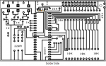
I have produced a PCB using all of the relevant diagrams however when I have come to put my PIC in, it says 'Hardware Not Recognised'. Is the circuit wrong or is it a faulty part?

Have used PICAXE 20X2 on the same computer fine so it is not a driver issue.

Included is a picture of the PCB.

PCB.JPG


Many Thanks,

Matt
 

Hemi345

Senior Member
If I'm looking at your circuit right, it looks like you put the 10K to ground before the 22K instead of after it.
 

nick12ab

Senior Member
  • You also have the download circuit wired as a potential divider - this won't work (on PICAXEs that have a schmitt trigger Serial In pin) unless you are using the RS232 download cable.
  • You have a lot of tracks running in between IC pins. It's possible (especially with school equipment that isn't very good) that one or more of these tracks are shorted to the IC pins.
  • You have zero decoupling capacitors - failure to have one in a circuit often causes unreliability. The usual is to have one 100nF capacitor near to the power pins of each IC.
  • You have no 'bulk' capacitor - every time your battery box is subject to vibration the cells can bounce, momentarily losing contact with the terminals, which will cause the PICAXE to reset with no 'bulk' capacitor. A 100µF capacitor is the usual choice.
  • Are those flying wires trapped under the IC socket in real life? I can't help but feel that most of those flying wires could have been eliminated by better PCB design too.
 

Mattc141

New Member
Hi,

Thanks for the replies.

The Flying Wires actually go over the IC Socket.

I tested with a multi meter previously and there seem to be no shorts.

For the moment I am not too worried about capacitors as I will add them later when the program is downloaded.

It seems then that the Programming Socket's Resistors have been wired up incorrectly. If it was to be programmed on another board, I assume it would work.
If not for a long period of time, enough for me to give a 30s demonstration.

Thanks,

Matt
 

hippy

Ex-Staff (retired)
It seems then that the Programming Socket's Resistors have been wired up incorrectly. If it was to be programmed on another board, I assume it would work.
Yes that should work. It should also work when the download cable is attached by just removing the 10K.

Plenty of places on the track side to easily connect the 10K to socket and 0V so it's not junk, can still be used as intended.
 

Mattc141

New Member
So you say I need to remove the 10K resistor that goes between IC Pins and then attach one to the foot of the programming socket connected to the 22K Resistor and Ground. *Foot B

Thanks.
 

nick12ab

Senior Member
So you say I need to remove the 10K resistor that goes between IC Pins and then attach one to the foot of the programming socket connected to the 22K Resistor and Ground. *Foot B
Yes. Right by the relevant pins on the download socket itself is fine.

For the moment I am not too worried about capacitors as I will add them later when the program is downloaded.
No reason why you can't have fitted them to begin with.
 

Mattc141

New Member
Will remove the 10K and attach a new one directly between Port B and the 0V Rail - Or is it the two 0V Pins?

To be honest my teacher has never told us anything about bulking or decoupling capacitors so I wasn't aware they needed to be included in the first place, however now I have had them mentioned and explained to be I will do a little research, scavenge some parts and make the necessary adjustments.

Many Thanks,

Matt.
 

Mattc141

New Member
Okay, now a slightly different issue. The Resistor swap worked fine as I can check the Firmware version of the PIC, however when trying to clear memory or program some code it comes up with Memory Verification Failed.

This has occurred on Bytes 255 & 3839 over 12 attempts. Changed the PSU from 6v to 4.5v. Am using AXE027

Unless the PIC is damaged in any way, would I be right in thinking that now the resistor set-up is fixed and the Jack operational, I can program it on another board and then simply put it in the IC Socket.

Matt.
 
Last edited:

russbow

Senior Member
I think you really need to put a large reservoir cap across your DC supply point and a 100nF across the picaxe supply pins.
 

Mattc141

New Member
What value do you mean by large? And when you say across the supply pins you mean between each +V Pin & Ground or the 2 +V Pins.

Many Thanks,

Matt
 

Mattc141

New Member
Hi there,

Thinking of rigging this up on strip board, after seeing it on RKE.

Caps.JPG

My question is, does the Capacitor setup shown seperatly go in between the two caps that follow the regulator.

Matt
 

nick12ab

Senior Member
My question is, does the Capacitor setup shown seperatly go in between the two caps that follow the regulator.
Those two extra capacitors are decoupling capacitors and the mystery circuit that you got them from probably had two ICs. Put one across +V and 0V for each IC.
 

Mattc141

New Member
The diagram is part of a schematic for a PICAXE 40 Pin Development Board from RKEducation, and there are 2 +V Feet on the 40X2 so this would make sense.
Will retry programming when this is complete and hopefully it should get no more errors.

Thanks,

Matt
 
Top