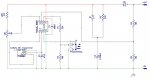
In a project I've been doing I've up against the limit on the number of pins on a PICAXE08M2. So I would like to use the input only pin C.3 to read the state of a photo resistor. This pin is incapable of doing ADC, so I'd need it to do a digital read.
I've looked at chapter 3, page 29 on the light dependent resistor, which implements a comparison circuit between the two resistances. If I put in a 50k resistor instead of the 10k and have a photo resistor that has 5k light resistance and 2M dark resistance, will the pin switch from High to Low as the lights are turned off and then switch back from Low to High when they come back on? If not, could I modify the resistances to achieve this? If so, how? I want to use the state change of the photo resistor to control the behavior of devices connected to the other output pins.
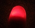
The second question I have is: I've read that when you use a Darlington driver the outputs do not drop to 0v when the attached PICAXE pin is dropped Low, but to some fraction of the driving voltage. I think I see this behavior as the LEDs (with 330ohm current limiting resistors) attached to 12v turn off and on, but also have a 3rd state where they dim dramatically but do not go off. How can I eliminate this dimmed state? Could adding resistance to each LED line achieve this or do I need to do something more elaborate?
I'd appreciate any help as I'm still new to all this. Thanks!
I've looked at chapter 3, page 29 on the light dependent resistor, which implements a comparison circuit between the two resistances. If I put in a 50k resistor instead of the 10k and have a photo resistor that has 5k light resistance and 2M dark resistance, will the pin switch from High to Low as the lights are turned off and then switch back from Low to High when they come back on? If not, could I modify the resistances to achieve this? If so, how? I want to use the state change of the photo resistor to control the behavior of devices connected to the other output pins.
The second question I have is: I've read that when you use a Darlington driver the outputs do not drop to 0v when the attached PICAXE pin is dropped Low, but to some fraction of the driving voltage. I think I see this behavior as the LEDs (with 330ohm current limiting resistors) attached to 12v turn off and on, but also have a 3rd state where they dim dramatically but do not go off. How can I eliminate this dimmed state? Could adding resistance to each LED line achieve this or do I need to do something more elaborate?
I'd appreciate any help as I'm still new to all this. Thanks!
")