Help with DS1307 RTC

Ben967

Member
Hi everyone,
Just a little project, reading time from a ds1307 RTC into a picaxe 18m2 and displaying it on an lcd. I know the lcd is working as have had it displaying test data correctly and RTC has been wired as shown in the picaxe i2c tutorial but I cannot figure out how to convert the data to show on the lcd, I have tried bcdtoascii with no luck.

Here's the test code:

Code:
 i2cslave %11010000, i2cslow, i2cbyte 'Set up ds1307

writei2c 0, ($00, $50, $11, $03, $25, $12, $03, $10) 'Set time

serout c.1,N2400,(254,1) 'Blank screen
pause 150    'Delay to blank screen
serout c.1,N2400,(254,128)

looop:
pause 1000
readi2c 0, (b0,b1,b2,b3,b4,b5)
'bcdtoascii b0,b6,b7 'Converts seconds to ASCII for display. The bit I'm not sure about!
serout c.1, N2400, (#b0) 'Display seconds
goto looop
 

hippy

Ex-Staff (retired)
BCDTOASCII should work so perhaps post your example code which doesn't.

Maybe try to get it working with SERTXD first so you can see what it would be doing on the Programming Editor Terminal and then move to putting it on the LCD.

One thing to remember is that BCDTOASCII creates ASCII characters so to output them that's simply ...

BcdToAscii b0, b6,b7
SerTxd( b6, b7 )

No #'s needed; that will print the value of the ASCII characters.
 

nick12ab

Senior Member
ou're sending with the Serout command #b0 rather than b6,b7 which is what you should send if you want the result from that bcdtoascii command since you've chosen those two variables.
 

RonCzap

Member
Here is some code I've been working on.

It lets you set the clock in 12 or 24 hour mode using the terminal window.

It uses a SparkFun serial LCD display but you could change it to use a different display.

NOTE: modified to use HSEROUT for LCD at 9600 baud
Code:
#picaxe 20m2
'#no_data
#com 4
#terminal 4800

Symbol hrs       = b0      ' Hours         $00-$23 		
Symbol hrs.bit5  = bit5    ' 0=am, 1=pm    (for 12 hour mode)
Symbol hrs.bit6  = bit6    ' 0=24, 1=12    hour mode  

Symbol am_pm     = bit8    ' am or pm (for 12 hour mode)
Symbol mode      = bit9    ' 12 or 24 hrs mode
Symbol AM        = 0
Symbol PM        = 1
Symbol Mode12    = 1
Symbol Mode24    = 0

Symbol mins      = b2      ' Minutes       $00-$59
Symbol secs      = b3      ' Seconds       $00-$59
Symbol month     = b4      ' Month         $01-$12
Symbol day       = b5      ' Day           $01-$31
Symbol year      = b6      ' Year          $00-$99
Symbol dow       = b7      ' Day of Week   $00-$06 ( 0=Sun, 1=Mon ... 6=Sat )
Symbol control   = b8      ' SQW I/O control   

Symbol decval    = b9
Symbol bcdval    = b10

Symbol idx       = b11
Symbol idy       = b12
Symbol cursor    = b13     'LCD cursor pos

'Sparkfun LCD constants 
symbol lcd_cmd     = $FE   'command prefix
symbol lcd_cmd2    = $7C   'special command prefix
symbol clrLCD      = $01   'Clear entire LCD screen
symbol displayOff  = $08   'Display off
symbol displayOn   = $0C   'Display ON
symbol noCurs      = $0C   'Make cursor invisible
symbol ulCurs      = $0E   'Show underline cursor
symbol blkCurs     = $0D   'Show blinking block cursor
symbol curpos      = $80   'set cursor  + position  (row 1=0 TO 15, row 2 = 64 TO 79)
symbol scrollRight = $1C
symbol scrollLeft  = $18
symbol curRight    = $14
symbol curLeft     = $10

symbol LCD         = C.0


EEPROM 0,("SunMonTueWedThuFriSat")

  hsersetup B9600_4,0

  PAUSE 1000                ; give time for PE terminal Screen to initialize

  HI2cSetup I2cMaster, $D0, I2cSlow, I2cByte

  hserout 0,(lcd_cmd, displayOn)
  pause 2000
  hserout 0,(lcd_cmd, clrLCD, lcd_cmd, noCurs)
  
  sertxd ("Enter 'y' to set date", cr, lf)
  serrxd [5000,ShowTime],("y")
  gosub SetClock

ShowTime:
  reconnect
  HI2cIn $0, (secs, mins, hrs, dow, day, month, year)
  if secs = 128 then             'clock not set
    gosub SetClock
  end if  
  mode = hrs.bit6                'get 12/24 hour bit
  if mode = Mode12 THEN
    am_pm = hrs.bit5             'get am_pm bit (HIGH = p.m.)
    hrs.bit5 = 0
    hrs.bit6 =0
'    hrs = hrs & %00011111        'clear bits 5 and 6
  else
'    hrs = hrs & %00111111        'clear bit 6
    hrs.bit6 =0
  endif

  gosub Show_LCD 
  pause 1000
  goto ShowTime

  end

Show_LCD:
  cursor = curpos + 2
  hserout 0,(lcd_cmd, cursor)
  bcdval=hrs  : gosub BCD2DEC : if decval < 10 then hserout 0,("0") end if : hserout 0,(#decval, ":")
  bcdval=mins : gosub BCD2DEC : if decval < 10 then hserout 0,("0") end if : hserout 0,(#decval, ":")
  bcdval=secs : gosub BCD2DEC : if decval < 10 then hserout 0,("0") end if : hserout 0,(#decval, " ")
  if mode = mode12 then 
    if am_pm = AM then
      hserout 0,("a.m.")
    else
      hserout 0,("p.m.")
    endif
  endif  

  cursor = curpos + 66
  hserout 0,(lcd_cmd, cursor)

  idx = dow-1
  idx = idx * 3
  for idy = 0 to 2
    read idx, decval
    idx = idx + 1
    hserout 0,(decval)
  next
  hserout 0,(" ")

  bcdval=month  : gosub BCD2DEC : if decval < 10 then hserout 0,("0") end if : hserout 0,(#decval, "/")
  bcdval=day    : gosub BCD2DEC : if decval < 10 then hserout 0,("0") end if : hserout 0,(#decval, "/")
  bcdval=year   : gosub BCD2DEC : if decval < 10 then hserout 0,("0") end if : hserout 0,(#decval)
  return   
  
 
SetClock:
  sertxd ("Year (e.g.11)", cr, lf)
  serrxd #decval : gosub DEC2BCD : year = bcdval
  sertxd ("Month (1-12)", cr, lf)
  serrxd #decval : gosub DEC2BCD : month = bcdval
  sertxd ("Day (0-31)", cr, lf)
  serrxd #decval : gosub DEC2BCD : day = bcdval
  sertxd ("DayOfWeek: 1=SUN 2=MON 3=TUE 4=WED 5=THU 6=FRI 7=SAT", cr, lf)
  serrxd #dow
  sertxd ("Mode (1=12hr 0=24hr)", cr, lf)
  serrxd #mode
  if mode = 0 then
    sertxd ("HH: 00-23",cr,lf)
  else
    sertxd ("HH: 01-12",cr,lf)
  end if
  serrxd #decval : gosub DEC2BCD : hrs = bcdval
  sertxd ("Minute (00-59)", cr, lf)  
  serrxd #decval : gosub DEC2BCD : mins = bcdval
  if mode = 1 then
    sertxd ("0=AM 1=PM",cr,lf)
    serrxd #am_pm
  end if
  secs = $00
  control = 0                 ' disable SQW output
  IF mode = Mode12 THEN
    hrs = hrs | %01000000     '$40   'set bit 6 high for 12 hr mode
  end if
  IF am_pm = PM THEN
    hrs = hrs | %00100000     '$20   'set bit 5 high for PM
  end if
  HI2cOut $0, (secs, mins, hrs, dow, day, month, year, control)
  return
  
DEC2BCD:
  bcdval = decval/10*16
  bcdval = decval//10 + bcdval
  return
  
BCD2DEC:
  decval = bcdval/16*10
  decval = bcdval//16 + decval
  return
 
Last edited:

Ben967

Member
Thanks for the help, I,m now getting sensible values, but the time on the RTC doesn't seem to be counting now:

Code:
 i2cslave %11010000, i2cslow, i2cbyte 'Set up ds1307

writei2c 0, ($21, $50, $11, $03, $25, $12, $03, $10) 'Set time

serout c.1,N2400,(254,1) 'Blank screen
pause 150    'Delay to blank screen
serout c.1,N2400,(254,128)

looop:
pause 1000
readi2c 0, (b0)
bcdtoascii b0,b6,b7 'Converts seconds to ASCII for display.
serout c.1, N2400, (b6,b7," ") 'Display seconds
goto looop
 

nick12ab

Senior Member
Not counting? Is the crystal connected properly and of correct speed? Do you mean you can't set the time at all (i.e. time is always 00:00:80), when you set the time it doesn't go up or you can't access it properly for reading (i.e. time always something really obscure and invalid)?
 

Ben967

Member
I can set the time and read it back fine, I have it displaying on the lcd now, but the seconds do not count up.
 

Ben967

Member
One more problem now, the RTC has been running for a few hours now and it is about half an hour off of the actual time!

Every two to three seconds the time seems to freeze for a second?
 

RonCzap

Member
One more problem now, the RTC has been running for a few hours now and it is about half an hour off of the actual time!

Every two to three seconds the time seems to freeze for a second?

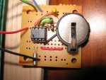
Is your chip and crystal on a breadboard or a PCB module or other???

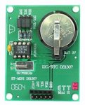
I have several DS1307/DS3231 modules. I made one, purchased one from Futurlec and bought a couple of Chronodot modules.

You should have a ground plane under the crystal but mine works well without it.

NOTE: the crystal and foil groundplane are positioned below the IC on the green board
Ds1307 RTC.jpgDS1307 Real Time Clock.jpg
 
Last edited:

hippy

Ex-Staff (retired)
Its on a breadboard at the moment
It could be dodgy connection to the crystal or elsewhere, or even the stray capacitance of the breadboard itself could be throwing things off or stopping the crystal oscillator.
 

RonCzap

Member
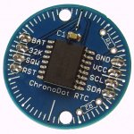
I really like the ChronoDot modules. They use the DS3231 and are much more accurate.
Plus they don't have an external crystal.

ChronoDot.jpg
 

westaust55

Moderator
Do you have the correct crystal connected. It must be a 12 pF 32.768 kHz.
Some crystals (even for other Dallas/Maxim products) are 6 pF 32.768 kHz.
Such difference will lead to timing errors. You may need to check with your supplier of the crystal (if not Rev Ed)


If it is on a breadboard, or far (relatively speaking ) form the DS1307 tha can introduce additional capacitance which will affect timing accuracy.


From the datasheet:
The internal oscillator circuitry is
designed for operation with a crystal having a specified load capacitance (CL) of 12.5pF.
 

John West

Senior Member
The purpose of the ground-plane is to isolate the tiny Xtal signal from any nearby signal traces. Adding one to a breadboard circuit likely won't help solve the problem of an intermittent oscillation. My guess is the same as some others suggest, circuit capacitance.

Clock crystals work with very small capacitances (and microamp signals) and need to operate in a physical circuit setup where those capacitances are carefully controlled, not on breadboards, where significant uncontrolled capacitances are to be expected.

Even the tiny lead capacitance of a good scope probe can stop a crystal RTC clock oscillator dead when attempting to look directly at the xtal signal with a 'scope.
 
Last edited:

tracecom

Senior Member
One more problem now, the RTC has been running for a few hours now and it is about half an hour off of the actual time!

Every two to three seconds the time seems to freeze for a second?
These two issues might not be related. Sometimes, even with an accurate setup, the output to the LCD gets behind the clock and has to skip to catch up.
 

nick12ab

Senior Member
You could cut the crystal pins very short so you can solder the xtal directly to those pins but the pins don't reach into the breadboard.
 
Top