Help to mount a tiny IC

tobyw

Member
I got a bit excited and bought an accelerometer IC from RS without really checking what I was getting.

When it arrived, it turned out to be almost microscopic! Here is the link

MMA7361LCT

So not exactly suitable for a breadboard.

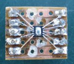
I was thinking maybe it would be possible to create my own little breakout board with the chip in the middle...and larger pins at the sides which I can connect to my picaxe easily. I googled surface mounting, and using flux and reheating with a hot air gun, it looks like it might be possible. I might as well have a shot, because the alternative is never use it anyway.

However, the videos and tutorials I have seen on the subject all seem to start with a PCB which already has a 'footprint' for the IC. And the pads all seem to be isolated. I can't see how they are connected to the rest of the circuit.

So I have two problems I am hoping people can help me with:

1. How is this kind of 'footprint' done..and how does it connect to the rest of the circuit. Can I draw one myself that tiny with a PCB and pen, then etch it all away. Or does it need to be a multilayer PCB or something?

2. I can't afford to buy any circuit making software. I've tried a number of free ones, but none of them seem to handle components of this size. Is there any free PCB software out there which you can recommend for making tiny circuits like this?

Thanks for any help you can offer :)
 

inglewoodpete

Senior Member
Help to mount tiny IC

The mind boggles.

Yes those chips are distressingly small. The "Enlarge" link of the RS webpage almost adds to the deception but read the specs: 3mm x 5mm.

If you haven't dropped it on the carpet already, Google "LGA 14 adapter" without the quotes.

Adapters like this one are available, adding a few dollars to your project but saving a few tears.
 

hippy

Ex-Staff (retired)
With care you can make your own breakout board;
That's impressive. I tried similar with a SOIC chip that had quite wide leg spacing and made a real mess of that so it does come down to skill, talent, experience and what equipment you have to hand.
 

srnet

Senior Member
However, the videos and tutorials I have seen on the subject all seem to start with a PCB which already has a 'footprint' for the IC. And the pads all seem to be isolated. I can't see how they are connected to the rest of the circuit.
It needs a matching set of Surface Mount pads on one side of the PCB. A lot of PCB packages, even the free ones, have footprints for this type of package, or you can draw your own.

It might be possible to DIY a PCB with pads this small, but it would need a fair bit of skill, and soldering them aint to easy either.

Most people would have PCBs for this type of board manufactured.
 

tony_g

Senior Member

tobyw

Member
Wow. Thanks to everyone for all the suggestions and links. I'm now dithering between trying to create my own pcb (more of a fun challenge, higher risk of failure) and buying an adapter (more expensive, still a risk of soldering failure)

In the end, I have a nasty suspicion I should just buy a mounted chip like eclectic's link...probably will work out cheaper. But isn't the fun in trying to do it yourself?....

PS. tony_g I downloaded design spark..looks cool but I am totally lost with it. Can't even work out how to make something the size it needs to be...!
 

inglewoodpete

Senior Member
I'm now dithering between trying to create my own pcb (more of a fun challenge, higher risk of failure) and buying an adapter (more expensive, still a risk of soldering failure)
Surface mount soldering is not as hard as you think. Another expense, though is some solder paste. You just have to use the girlfriend's/wife's/mother's electric frypan/skillet/flat-toaster when they're out:). Google that too or look on you tube.
 

Haku

Senior Member
3 weeks ago I received 3 MMA7361's on pre-made boards:


Onboard power LED, manufacturer recommended capacitors & 3.3v regulator for the ability to run it from 5v. The zero-g pin is pretty cool, attach an LED and watch it go bright when you drop the powered-up board ;)

Delivery of mine from this eBay seller only took 10 days from China, if you want one quicker from a UK seller be prepared to pay over double.
 

womai

Senior Member
Since you already have bought the chip, there is no harm done in at least trying to mount it yourself before thinking about buying a pre-mounted one. IMHO the best (least expensive) method is the "dead bug" option, already shown in a previous post on this thread. Dead bug because you turn the chip on its back so the contact pads are on top. The solder on thin wires. You can get those from flexible multi-strand (Litz) wires you find at any hobby shop - just cut open the insulation and voila. A fine tip for your soldering iron also helps, as does desoldering wick (braided copper) in case you accidentally create solder bridges between pads.
 

tony_g

Senior Member
PS. tony_g I downloaded design spark..looks cool but I am totally lost with it. Can't even work out how to make something the size it needs to be...![/QUOTE said:
when you have some time to just mess around with it you should eventually be able to create custom pad sizes for things you want to do smt style but are not in the library, it takes a bit of perseverance and constant use of the measure tool to make sure the pads are as per the device datasheet guides and pad spacing is correct but eventually it gets to become more user friendly and straightforward.

im now having fun with double sided boards for smt, now just have to get a new laser printer as mine looks like its going downhill and leaving the odd thin patch or line through the artwork that will just get etched though, oh well an early xmas present for me then to go buy lol ;)
 

Paix

Senior Member
I'm with Srnet at post #5 and Womai at post #13. piece of veroboard, with the tracks cut, and vero or header pins inserted. Tracks down and the chip glued dead bug style on the top plain surface of the board. Take a bit of stranded hook up wire and strip a four or five inch length, taking the seven strands for use connecting the pins to the chips.

Tin the end of the wire for a good length and attach to the pins in the board with a single turn around them and solder, so that there is a length of wire still available in the direction of the chip. Carefully clip the wire and with tweezers or a wooden toothpick maneuver the clipped and tinned end of the wire onto the appropriate tag, with a little slack and then with a small element on your soldering iron, touch the wire/pad and hopefully the solder should flow and that will be one less connection that you need to complete.

Good luck. Make sure that your lighting is good and that the small board and it's pins are secured, unable to move about, before you begin attempting to solder.
 
Top