Help reading battery voltage

wagp

New Member
I would like to build a device that would accurately read and display the voltage from the engine and house batteries in my motorhome. Both are 12 volt systems. I image a PICAXE board with the necessary switches and "stuff" that will select which set of batteries to read and display.

My project has more going on, but reading and displaying the two different voltages has me stumped.
I'm new to all this and not sure how to get started.

Thanks,
wagp
 

KeithRB

Senior Member
What has you stumped?
You need to run wires from the batteries to where the PicAxe is and use a voltage divider to drop the 20 V down to 5. Connect the wires to a valid ADC port on the PicAxe. Then use readADC which will scale the 0 - 20 V to 0 - 255.

(I used a maximum of 20 V because Car electrical systems are really nasty and have lots of transients and noise.)
 

KeithRB

Senior Member
AXE133Y or AXE134Y OLED module. Works great with the PicAxe.

But I don't know whether you want to read it from 2 feet or 20 feet...
 

premelec

Senior Member
Note that the reference voltage for reading READADC is the V+ voltage on the PICAXE so this should be a stable known voltage. [implies internal reference stuff or external voltage regulator]. Note that the voltage regulator and PICAXE draw a small current - if the vehicle is put in storage they should be disconnected.
 

SAborn

Senior Member
Do you have a understanding of the basic circuit you will need for your picaxe battery monitor.

In most cases with a LCD you can read both batteries and display them on seperate lines, without the need to switch between each battery.

If you buy a project board with the picaxe chips, try to select one that has a place for a voltage regulator on the board, as you will need it for 12v to 5v operation.
 

wagp

New Member
I have "sort" of an understanding. A retired electrical engineer friend is helping, but he's out of town at the moment.
I'm a retired computer programmer, so together we are interested in building this battery monitor.
We both have motorhomes and thought it would be fun, educational and useful to work on this.
 

SAborn

Senior Member
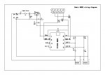
The basic circuit is rather simple and attached is a schematic of the very basics of the circuit.
It shows an 08m2 chip but that can be any chip and will depend on what type of LCD display you choose to use, also it dont show the display as we dont know what that is as yet.

Note both batteries must have a common connection of ground (-) to both batteries at all times, V+ can be switched on or off on either battery without effecting the circuit.

R4 and R5 (R6 and R7 for battery 2) make up the voltage divider to drop the 12v (or greater) to a voltage below 5v max, the resistor values given for R4/R5 and R6/R7 will work, but might need some fine tuning to suit the range better (i allowed 0-20v range).

It was a quick schematic of a previous circuit with the voltage dividers added, so others might comment to use a different Vreg for automotive use............etc.....etc.

Battery monitor.jpg

View attachment Battery monitor.pdf
 

wagp

New Member
Thanks SAborn for the diagram.
I've ordered a AXE133Y display (in a kit with a pre-programmed computer).
I'll be learning about this while waiting for my EE friend to return.
 

bluejets

Senior Member
I think you will need to supply a diagram of your set-up as most 2 battery arrangements are either charged from the one source or have a 3 way selector for loading. (i.e. battery1/ battery2/ or both.) or a combination of both systems.
 

SAborn

Senior Member
BJ, what difference will it make to how the batteries are charged, he only wants to display the battery voltage.
 
Last edited:

SAborn

Senior Member
I've ordered a AXE133Y display (in a kit with a pre-programmed computer).
Other than the AXE133Y display, what other picaxe chips and hardware have you ordered?

With the AXE133Y being serial, i think you can do all you want with the 08m2 chip.
 

wagp

New Member
I've only ordered a kit which comes with the AXE133Y and includes a "pre-programmed" 18M2. Not sure what else is in the kit.
I thought the kit would give me some experience assembling things and let me get my "feet wet" working with some of the components.
 

KeithRB

Senior Member
It matters because if the grounds are isolated it might complicate things a bit back at the PicAxe, requiring relays, for example.
 

campo

New Member
You will want to assess factors like heat range. If you do that, you will use some kind of heat range indicator, and the chances is great that it will generate a current that you have to assess.
 
Last edited:

Axel87

Senior Member
Hello all,
I am working on a project that I believe is similar to this, but looking for a bit more information to get me started.
Making a psu unit, it is a simple design-12v Supply, 24V supply- these are both separate regulated psu's, and a desktop psu that I want to make as a variable supply (0-24V).
The fixed psu's are just going to be used as a convenience, if I need.
I have 2 7 segment LEDs that I want to display the selected voltage. The way I imagine this circuit would have a 3 way switch (12v and 24V) and the last connecting to a pot to select voltage (0-24V dc.)
I have read a bit on the readadc command, but cannot find alot of info on it, so I dont know if I am heading in the right direction.
What are the capabilities of this "command" or input? If I send 24v to the chip, I would imagine it would fry it, correct? :confused:
I also imagine that I will need to somehow use one 08m2 chip to drive both segment displays, which I believe this can do? Somehow divide the digit display. example 12V input- (1) output on A display (2) output to B display. ??
I apologize if this is in another thread already.
This is my first real project besides turning on and off an led, so dont make it too easy for me ;) Gotta learn the hard way
If you have any ideas as were I can reference to get me started on this path, any help would be appreciated!
Thanks
 
Last edited:

Axel87

Senior Member
If I deduced that I would need a voltage divider for all seperate supply's, would that be correct?
example- a divider to drop the 12v supply to a set known value ie 2v? and the 24 could be 4V?
If this is correct, I dont have any ideas at this time to do a variable (0-24V.) But I believe I saw a post a while back that someone made a similar design.
Thanks again!
 

AllyCat

Senior Member
Hi,

It's generally better to start a new thread, so that we don't have to read through 21 previous posts (which I haven't) that may, or may not, be relevant to your particular requirement.

But yes, you are correct that you mustn't put 12 or 24 volts directly onto any PICaxe pin, so use a resistor potential divider network to keep the input voltage within the range of the supply/ground rails.

I also imagine that I will need to somehow use one 08m2 chip to drive both segment displays, which I believe this can do?
AFAIK not without significant additional hardware. But what do you intend to display on just two 7-segment (LED?) displays? The simpest method is to connect the 14 segments to separate PICaxe pins, so you'd need at least a 20M2. With multiplexing you might just fit it on a 14M2 but it's hardly worth the extra software complexity, etc. However, an advantage of multiplexing is that you'd only need 7 current-limiting resistors instead of 14.

READADC should easily be accurate enough for a two-digit display, but if you need more resolution then there is READADC10, at which point there are other factors which need to be considered such as the reference voltage accuracy. The basic information is in Manual 2, in the READADC(10), CALIBADC and maybe FVRSETUP sections, etc..

Cheers, Alan.
 
Top