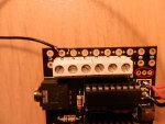
HELP PLEASE | LCD Modules

Newone

New Member
Hello,

I have recently purchased a Picaxe 18 starter kit, along with a 16X2 LCD and a separate driver kit. The starter kit uses an 18X pic and the LCD driver uses a 18M2 pic. I have tried to link the systems together, but in vain. For the moment, I am struggling to even get a 'Hello' on the screen!!!

I anyone is able to send me a pin-out diagram of how to connect it all, also a sample program to get a simple message up I would be very grateful.

I am trying to, 'self-tutor' and don't seem to be having too much luck.

Your time is much appreciated
 

bfgstew

Senior Member
Welcome to the Forum and to Picaxe.

Should be a small 3 pin header marked with 0V, +V and IN, simply connect a wire from your 0V line to the pin marked the same, a wire from your 5V supply to the pin marked the same and a wire from a pin off the 18X which will be your SERIAL OUT line to the last pin on the header marked IN.
I am unable to furnish you with a sample code as am using works PC so no access to PE, plenty in the forum if you search hard enough.
You will need to know what pin you have connected the LCD screen to as this will be used in your code to 'send' data to the screen - serout B.7, N2400,(254,128,"HELLO")
B.7 is an example, you need to insert your actual pin number in place of it.
Also read and learn the 3 manuals for code techniques and examples.
 

westaust55

Moderator
Welcome to the PICAXE forum.

A good practice to get into is to provide a link to the webpage or datalink for the hardware you have.

Is the starter kit a CHI030a?
http://www.picaxe.com/docs/chi030a.pdf

If so the outputs at the edge are through a ULN2803 which:
(A) has open collector outputs, and
(B) inverts the signal

You will need to connect the LCD display data wire directly to a the PICAXE pin being used as the output for your SEROUT commands.
 

inglewoodpete

Senior Member
If the board is a recently purchased CHI030a then there will be a row of solder pads between the two chips. Choose one of the port B pins and extend a wire from it to the serial input pin of the 033. Ensure you have the 0v line connected between both boards too. In your code, make your SerOut command point to the chosen pin.

You haven't said, so I'll ask the question: Does the AXE033 boot up with a message on the screen? It should.
 

Newone

New Member
Hi,

Thanks for contributing. Unfortunately, the screen stays completely blank when I power it up!!!

Can you see how confused I am!!
 

bfgstew

Senior Member
OK, do not panic.
Time to help us help you, you need to post a clear image of your set up both board and LCD unit showing as much detail as possible and the code you are using to communicate with to the LCD, the more info the forum gets, the easier it is to solve a problem.
 

Newone

New Member
Thanks for the tips:

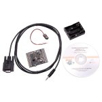
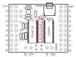
I have looked in the documentation that came with the starter pack. Unfortunately, it uses a slightly different board layout to the one which I have. (Unusual I know) I have attached an image of what my board really looks like. It does not have holes down the middle in between the chips.

To drive the LCD, I have got a AXE132 driver board, and a LED008 LCD to display the message.

Just to clarify, I have not yet managed to get any start-up message.

Picaxe trianer starter pack.jpg
 

bfgstew

Senior Member
A picture of your actual set up rather than an image of what you have would help greatly, this will identify any errors.
 

Newone

New Member
Hi,

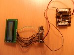
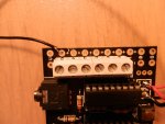
Please see attached images. I hope that you will be able to see what you need to from these.

The connection from the LCD driver to the display looks a bit messy as it is done with wires, rather than pins. I have checked the connections thoroughly, and there doesn't seem to be a problem there.
 

Attachments

nick12ab

Senior Member
Please see attached images. I hope that you will be able to see what you need to from these.=
The signal wire is connected to the output of the darlington driver. This wire needs to be connected directly to the PICAXE output pin.

Where is the power supply connected? EDIT: I see two extra wires connected to the same pads as the power connections for the LCD. That's OK.

Have you tried adjusting that contrast control? Why have you added those green and white wires to the LCD - it has no backlight so those wires do nothing.
 

Newone

New Member
Sorry to be so dumb, but exactly where is it best to connect the output signal wire to??? As far as the green and white wires go, 'They are no longer in existence' (as you can tell I am very inexperienced with this!!!)
 

nick12ab

Senior Member
Sorry to be so dumb, but exactly where is it best to connect the output signal wire to??? As far as the green and white wires go, 'They are no longer in existence' (as you can tell I am very inexperienced with this!!!)
There should be a bunch of pads on the PCB all in a row between the two ICs (see the picture) - these are connected directly to the PICAXE output pins - connect the signal wire for the serial LCD to the pad marked B.7 (or a different pin if you don't want to use B.7). You will need a soldering iron to do this.

If you don't want to solder, remove the ULN2803 and connect the signal wire for the LCD to the pin on the socket that is connected to pin B.7.
 

Attachments

Newone

New Member
There are only 3 holes in between the two ICs. These have got a label (X1)

Also, should I be getting a startup message even if it is only connected to the LCD driver board?
 

nick12ab

Senior Member
There are only 3 holes in between the two ICs. These have got a label (X1)
Your board appears to be the original CHI030 which doesn't have the pads - the three holes are for a resonator for a PIC microcontroller. However your board also has a three pin header (circled) which isn't mentioned in the datasheet except for a mystery test header which has one pin connected to an output. Check if any of these pins are connected directly to a PICAXE output and if they are, you can connect the signal wire for the serial LCD here. If the other pads are +V and GND then that is even better because you can neaten up the wiring by having the signal wire and the two power wires together on the PCB.

Also, should I be getting a startup message even if it is only connected to the LCD driver board?
Only if the contrast is correct and the PICAXE-18M2 on the AXE133 PCB has been programmed to do so.
 

Attachments

Newone

New Member
Your board appears to be the original CHI030 which doesn't have the pads - the three holes are for a resonator for a PIC microcontroller. However your board also has a three pin header (circled) which isn't mentioned in the datasheet except for a mystery test header which has one pin connected to an output. Check if any of these pins are connected directly to a PICAXE output and if they are, you can connect the signal wire for the serial LCD here. If the other pads are +V and GND then that is even better because you can neaten up the wiring by having the signal wire and the two power wires together on the PCB.

Only if the contrast is correct and the PICAXE-18M2 on the AXE133 PCB has been programmed to do so.
Thanks for that, I have tried it, but to no avail.

I was using the serout command. Is this the right thing to do?
 
Last edited:

nick12ab

Senior Member
Thanks for that, I will try it now.
Try what now?

What do you suggest as a test program?
For what?

There's more than one thing in my post you could be referring to so in the future when you reply please could you put the bit of text you are replying to in [QUOTE][/QUOTE] tags, reply below that, then if there is more text you want to reply to repeat that underneath just like I've done in this post.

If you're talking about the Test pads then this requires you to check the hardware - visually examine the PCB to see what the three pins on the three pin header I circled in the picture connect to.

If you're talking about the welcome message, then program the PICAXE-18M2 on the AXE133 PCB with the AXE133 firmware below:
Code:
; AXE133 Serial LCD/OLED using PICAXE-18M2
; Emulates basic serial operation of the popular AXE033 module
; CPS, May 2011
; v2 18/01/2012

#picaxe 18M2

; ********************************************
; Note you must uncomment just one of these two options
; depending on whether you have an LCD or OLED module
;#define use_OLED
#define use_LCD
; ********************************************


; Supported Commands
; 0-7, 8-15	CGRAM characters
; 16-252	normal ASCII characters, according to selected character map table
; 253, X	display 16 character pre-saved message from EEPROM memory, X can be 0-15
; 254, X	LCD command, X can be 0 to 255 
; 255, X	control outputs C.2, C.1, C.0 (via lower 3 bits of X)
;		So, if using a backlit LCD with the active low transistor driver
;		on output C.2, then 255,%000 switches backlight on and 255,%100 switches off


#define use_welcome	; display the welcome message upon power up
symbol line_length = 16	; change to 20 for displays with 20 character lines

symbol baud = N2400_16	; Serial baud rate 2400,N,8,1. Note main program runs at 16MHz

symbol spare0 	= C.0 ; spare output 0
symbol spare1 	= C.1 ; spare output 1
symbol spare2 	= C.2 ; spare output 2 (or optional backlight)
symbol backlight 	= C.2 ; optional backlight control for backlit LCDs, active low
symbol RX		= C.5	; serial receive pin
symbol enable 	= C.6	; LCD enable
symbol rs 		= C.7	; LCD RS 


; LCD data pins are on B.0 to B.7

; Store the 16 character user defined messages in EEPROM data memory
; First two messages are optionally used as welcome message

; If using a display with 20 characters you will need to edit 
; the start addresses to be multiples of 20 (currently at 16) 
; and add 4 characters to each message.
; Please remember 4 line displays always use the strange 1-3-2-4 layout.

#ifdef use_OLED		
EEPROM $00, ("  Serial OLED   ") 	; store msg in the EEPROM memory
#else
EEPROM $00, ("   Serial LCD   ") 	; store msg in the EEPROM memory
#endif


EEPROM $10, (" www.picaxe.com ") 	; store msg in the EEPROM memory

EEPROM $20, ("This is msg 2   ") 	; store msg in the EEPROM memory
EEPROM $30, ("This is msg 3   ") 	; store msg in the EEPROM memory
EEPROM $40, ("This is msg 4   ") 	; store msg in the EEPROM memory
EEPROM $50, ("This is msg 5   ") 	; store msg in the EEPROM memory
EEPROM $60, ("This is msg 6   ") 	; store msg in the EEPROM memory
EEPROM $70, ("This is msg 7   ") 	; store msg in the EEPROM memory
EEPROM $80, ("This is msg 8   ") 	; store msg in the EEPROM memory
EEPROM $90, ("This is msg 9   ") 	; store msg in the EEPROM memory
EEPROM $A0, ("This is msg 10  ") 	; store msg in the EEPROM memory
EEPROM $B0, ("This is msg 11  ") 	; store msg in the EEPROM memory
EEPROM $C0, ("This is msg 12  ") 	; store msg in the EEPROM memory
EEPROM $D0, ("This is msg 13  ") 	; store msg in the EEPROM memory
EEPROM $E0, ("This is msg 14  ") 	; store msg in the EEPROM memory
EEPROM $F0, ("This is msg 15  ") 	; store msg in the EEPROM memory

;initialise LCD
init:
	gosub LCD_init 		; initialise LCD

; display welcome message if desired
#ifdef use_welcome	
	let b1 = 0			; message 0 on top line
	gosub msg			; do it

	low rs			; command mode
	let pinsB = 192		; move to line 2, instruction 192
	pulsout enable,1  	; pulse the enable pin to send data.
	high rs			; character mode again
	
	let b1 = 1			; message 1 on bottom line
	gosub msg			; do it
#endif		
		
; main program loop, runs at 16MHz

main:

	serin RX,baud,b1			; wait for the next byte

	; NB keep character mode test as first item in this list to optimise speed
	if b1 < 253 then
		let pinsB = b1 		; output the data
		pulsout enable,1  	; pulse the enable pin to send data.
		goto main			; quickly loop back to top
	else if b1 = 254 then
		low rs 	     		; change to command mode for next character
		serin RX,baud,b1		; wait for the command byte
		let pinsB = b1 		; output the data
		pulsout enable,1  	; pulse the enable pin to send data.
		high rs			; back to character mode
		goto main			; quickly loop back to top
	else if b1 = 253 then
		serin RX,baud,b1		; wait for the next byte
		gosub msg			; do the 16 character message
		goto main			; back to top
	else ; must be 255
		serin RX,baud,b1		; wait for the next byte
		let pinsC = b1 & %00000111 | %10000000
						; output the data on C.0 to C.1, keep RS high
		goto main			; back to top
	end if


; power on LCD initialisation sub routine
LCD_init:
	let dirsC = %11000111	; PortC 0,1,2,6,7 all outputs
	let dirsB = %11111111	; PortB all outputs


#ifdef use_OLED
	; Winstar OLED Module Initialisation
	; according to WS0010 datasheet (8 bit mode)

	pause 500 			; Power stabilistation = 500ms

	; Function set - select only one of these 4 character table modes
	;let pinsB = %00111000 	; 8 bit, 2 line, 5x8 , English_Japanese table
	let pinsB = %00111001 	; 8 bit, 2 line, 5x8 , Western_European table1
	;let pinsB = %00111010 	; 8 bit, 2 line, 5x8 , English_Russian  table
	;let pinsB = %00111011 	; 8 bit, 2 line, 5x8 , Western_European table2
	
	pulsout enable,1  	; 
		
	let pinsB = %00001100	; Display on, no cursor, no blink
	pulsout enable,1 	

	let pinsB = %00000001 	; Display Clear
	pulsout enable,1
	pause 7			; Allow 6.2ms to clear display

	setfreq m16			; now change to 16Mhz

	let pinsB = %00000010 	; Return Home
	pulsout enable,1

	let pinsB = %00000110 	; Entry Mode, ID=1, SH=0
	pulsout enable, 1


#else	
	; Standard LCD Module Initialisation
	pause 15 			; Wait 15ms for LCD to reset.

	let pinsB = %00110000 	; 8 bit, 2 line
	pulsout enable,1  	; Send data by pulsing enable
	pause 5 			; Wait 5 ms
	pulsout enable,1 	 	; Send data 48 again
	pulsout enable,1  	; Send data 48 again
	
	setfreq m16			; now change to 16Mhz

	let pinsB = %00111000 	; LCD  - 8 bit, 2 line, 5x8  
	pulsout enable,1
			
	let pinsB = %00000001	; Clear Display
	pulsout enable,1 	
	pause 8			; 8 = 2ms at 16MHz
	
	let pinsB = %00000010 	; return home
	pulsout enable,1

	let pinsB = %00000110	; Entry mode
	pulsout enable,1 	
	pause 1			

	let pinsB = %00001100	; Display on, no cursor, no blink
	pulsout enable,1 	
#endif
	
	high rs			; Leave in character mode
	return


; display message from EEPROM sub routine
; message number 0-15 must be in b1 when called
; uses (alters) b1, b2, b3, b4
msg:
	let b2 = b1 & %00001111 * line_length
						; EEPROM start address is 0 to 15 multiplied by 16
	let b3 = b2 + line_length - 1 ; end address is start address + (line_length - 1)
	for b4 = b2 to b3			; for 16 times
		read b4,b1			; read next character from EEPROM data memory into b1
		let pinsB = b1 		; output the data
		pulsout enable,1  	; pulse the enable pin to send data.
	next b4				; next loop
	return
	
; Check end user has defined just one type of display
#ifndef use_OLED
#ifndef use_LCD
#error "Oops - no OLED / LCD type defined at top of program!"
#endif
#endif

#ifdef use_OLED
#ifdef use_LCD
#error "Oops - both OLED / LCD types defined at top of program!"
#endif
#endif
 

westaust55

Moderator
How exactly have you checked the circuit?

Do you have a multimeter?
If so then test to. And sure that you:
(A) have a electrical connection between each boards from the driver to the LCD display
(B) do not have any shorts/bridges between adjacent pins or wires where you have soldered parts and wires in place.
P
Others have mentioned already that you should get a message displayed from the AXE132 to the LCD even without the starter pack connected.
Until you get that message there no little value in worrying about the connections or code from the CHI030 starter kit.
If contrast is the problem then adjusting the potentiometer on the AxE132 board should show something on the LCD.
Even if the LCD does not initialize and show a message you should see a row of black squares in the top line of the LCD.
 

Newone

New Member
How exactly have you checked the circuit?

Do you have a multimeter?
If so then test to. And sure that you:
(A) have a electrical connection between each boards from the driver to the LCD display
(B) do not have any shorts/bridges between adjacent pins or wires where you have soldered parts and wires in place.
P
Others have mentioned already that you should get a message displayed from the AXE132 to the LCD even without the starter pack connected.
Until you get that message there no little value in worrying about the connections or code from the CHI030 starter kit.
If contrast is the problem then adjusting the potentiometer on the AxE132 board should show something on the LCD.
Even if the LCD does not initialize and show a message you should see a row of black squares in the top line of the LCD.
Hi,

I have checked the circuit with a multimeter, and I am getting power at both the driver board and the LCD.

I accept what you say about not worrying about the connections and code in the CHI030 starter pack, but unfortunately, the LCD module does not even flicker or show any signs of display.
 

nick12ab

Senior Member
I have checked the circuit with a multimeter, and I am getting power at both the driver board and the LCD.

I accept what you say about not worrying about the connections and code in the CHI030 starter pack, but unfortunately, the LCD module does not even flicker or show any signs of display.
But have you tried adjusting the contrast control? You haven't stated that you have done this yet.
 

westaust55

Moderator
You have checked the circuit which I presume was for continuity.
Have you also check for shorts/solder bridges between adjacent pads/pins/wires on each board?
 

Erik66

New Member
I have exact the same problems with my two LCDs I ordered.
The display does not do anything. The PICAXE responds normal. I checked for shorts/solder bridges (as possible though the AXE 133 boards are directly mounted to the displays) and also reprogrammed the PICAXE with the firmware of this thread. Also the change of contrast does not do anything. Power supply was 4,5V (3*AA) and also 5V (stabilized Power Supply). The display remains dead.
Any suggestions?

Thanks
Erik
P.S. Please excuse my bad English.
 

westaust55

Moderator
Welcome to the PICAXE forum.

Is the LCD display also from the Rev Ed PICAXE store?
If elsewhere please provide a link to the Datasheet.

Have you set the AXE132 initialization for the type of display ? LCD versus OLED.

If you cannot even see square blocks in the top row of characters when the power is applied either the display could be dead or it has initialized.
What happens if you remove the 18M2 from the AXE132 interface board then apply power and adjust the contrast?
Wih the 18M2 removed the display cannot initialize and you should see black block characters in the top row.
 

Erik66

New Member
Hello westaust55.

Thank you for your warm welcome.
It is the budget display from Rev Ed PICAXE store.

With the 18M2 inserted it was not possible to set the contrast with the poti.
When I removed the 18M2 it was possible to set the contrast with the poti (square blocks in the top row).
After inserting the 18M2 again the display works fine and the contrast ist adjustable.
Same behaviour on both of my displays. Thanks for the tip to remove the 18M2.

Greetings
Erik
 
Top