HELP: Picaxe + RC Drone Radio Transmiter

macsoft

Member
Hi there.
I've long been a fan of picaxe, and RC flying stuff. So what about combining them?
I have a drone for aerial footage, a DJI Phantom 2 vision +.

The transmitter is a basic RC quad transmitter with no way to do mixes on the channels.
In one of the sticks of the remote, when I turn it, its like doing a panoramic with a camera. But.. I want to only turn the stick like 10%.. anymore and the movement is too fast.

I wanna add a switch to my remote, that does exactly that: limit the travel of the stick to 10%.
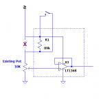
The sticks are basically connected to normal POTs.
Is there a way I can achieve this with picaxes?

THanks in advance
 

goom

Senior Member
One potential way of achieving this would be on the drone itself. You could intercept the receiver output, feed it into any Picaxe using PULSIN. You can use a very simple program to scale the input pulse, then output it to the servo using PULSOUT. I would be inclined to scale it non-linearly so that you can still achieve the same travel, but reduce the sensitivity near the center position. This would be essentially the same as using "exponential" on a fancy radio transmitter. The timing of the pulses would be self regulated at the same rate (approx. 50Hz) as the receiver output. You could even add a potentiometer read with ADC to enable tuning of the amount of "exponential"

Alternatively you could hack into the transmitter potentiometer connected to the stick. You would need to disconnect each end of the pot. and add resistances in series. The larger the resistance, the lower the amount of travel at the receiver end. You could add a DPDT switch to have the resistors in or out of circuit, effectively mimicking the "dual rate" switch found on "fancy" transmitters. One setting for normal flying, one for slow panning.
 

macsoft

Member
first of all, thanks for your input.

I don't want to do it on the receiver side for safety. I want to be able to turn it on and off on the remote itself.

About the gain on NAZA...I didn't thought of that thanks, that can be a fix. But i need to turn it on and off like a mix on a more advance radio. the NAZA assist has to be done on the computer pre-flight.
Any more ideas?
 

eggdweather

Senior Member
OK so you would need to disconnect the centre connection of the Yaw control stick potentiometer - the controlling input to the transmitter board, then apply that to a picaxe ADC input (the DJI uses 4xAA cells so that's about 0-6volts maximum swing from the pot, but you should measure the actual range), then having got your value in the picaxe, apply your control then output using a DAC output to the transmitter control input you just disconnected from the pot. The code then needs to scale down stick movement and limit the maximum value (10%) that can be applied to the transmitter.

If for example you get an ADC input maximum of 500 for maximum right yaw stick input limit that to 50 or divide by 10 then apply 50 to the DAC output and hence your Transmitter control input. In pseudo language speak:

start:
control-input = Read ADC input
control-input = control-input / 10 (REM or greater than 10 for less control output)
if control-input > 50 then control-input = 50
DAC output = control-input
GOTO start

You need to determine / measure the DJI Tx control input voltages to know if you need to scale down or up the voltage to the Picaxe, if too high then scale down to the maximum allowed input or too low then add an amplifier stage.
 

Goeytex

Senior Member
You don't really need a Picaxe or other micro-controller for this fairly simple modification. Just add a resistor that switches in and out of the circuit and then (if needed) buffer the output with a true rail to rail opamp.

Something like the diagram below should work. However the values depend upon actual measurements of the existing circuit. I assumed 5V and a 10K pot. Actual values are likely to be different. I show an LT1368 OPAMP but there are other are rail to rail choices that are not flea-sized SMT.
 

Attachments

macsoft

Member
Well being a hardware guy, my first thought was: I'll just use a DPDT switch and an new pot, and I can seitch between the original pot and my pot I can set with the value I want.
But since I'm loving our little picaxes I has hoping for a electronic solution :)

eggwaether, your idea seams great, but I'll a little foggy on the details. I know how to dear ADC input with a picaxe, but can it output DAC? or is that an external component?

I just remembered a more elegant possible solution:
The Transmitter (as most do) has a training port on the back.
I guess this is a serial port that you connect to the PC to play simulators with the transmitter.
But I know some remotes can connect to another remote to "train" the newbie flying.
What it there is way I can send Serialout commands from my picaxe to the training port?
I'm not sure this remote has "serial input" capability and I can't find documentation supporting it. But it would be a great idea to control all of the remotes functions, no?
Let me ear your thoughts please :)
 

goom

Senior Member
As Goeytex and I have said, the simple solution is to add switched resistors as shown in his schematic. You would need 2 resistors, one on each side of the existing potentiometer, in order to maintain the same neutral position. You could even use small trimmer potentiometers in order to fine tune to your requirements. I suspect that an opamp buffer would be unnecessary, but simple enough to find out by trying it.
A double pole single throw switch, 2 resistors (or potentiometers) and some wire is all that would be required. Why try to make things more complicated?
 

macsoft

Member
I'm not trying to complicate. I'm sure that solution works, thanks for the idea. But a picaxe in the mix would be more customizable and If I can, I prefer a solution that does not alter the radio what so ever.
The serialout on the training port solution would fix all that.
Has someone interfaced the serial port on a RC transmitter before?
 

srnet

Senior Member
The serialout on the training port solution would fix all that.
Has someone interfaced the serial port on a RC transmitter before?
The 'serial port' is very likley the PPM output from the transmitter.

Your chance of reading and measuring the entire PPM steam for all the channels, doing some sums to mix and match some of the channels and resend them all to a new PPM stream are remote with a PICAXE and interpreted basic.
 
Last edited:

macsoft

Member
The 'serial port' is very likley the PPM output from the transmitter.

Your chance of reading and measuring the entire PPM steam for all the channels, doing some sums to mix and match some of the channels and resend them all to a new PPM stream are remote with a PICAXE and interpreted basic.
I've got a Logic analyser, and a scope. I've successfully done some IR hack and RF hack with these tools and a picaxe using pwmout and pauseus commands. I don't see this being much different.
It would just save me a lot of time if someone had done it before.
I don't see the picaxe being limited for this, but I would like to know why you see it like so.

I've just found this: http://www.min.at/prinz/?x=entry:entry130721-182227
Some guy as done the same with some other radio and an arduino.
But for his radio it was known how to turn ON the trainee function.. problem is I still haven't found how to do it on mine
 

goom

Senior Member
Do you have a socket for a training link and a switch to activate training mode on your transmitter?
My understanding of the training concept is that all operator control inputs come from the training transmitter when "training mode" is selected on the master transmitter. Hence, if you could implement training mode, then you would have to provide all of the required inputs from another source (e.g. PICAXE). In other words you would need another set of input joysticks for input to the PICAXE, which would modify one or more inputs and then assemble and translate them into suitable serial protocol (PPM stream?), and output to the training jack.
I wish you the best of luck with the significant hardware and software challenges that this appears to have.

Four pieces of wire, two resistors, one switch and a soldering iron looks like a compelling route to me.
 

macsoft

Member
Do you have a socket for a training link and a switch to activate training mode on your transmitter?
My understanding of the training concept is that all operator control inputs come from the training transmitter when "training mode" is selected on the master transmitter. Hence, if you could implement training mode, then you would have to provide all of the required inputs from another source (e.g. PICAXE). In other words you would need another set of input joysticks for input to the PICAXE, which would modify one or more inputs and then assemble and translate them into suitable serial protocol (PPM stream?), and output to the training jack.
I wish you the best of luck with the significant hardware and software challenges that this appears to have.

Four pieces of wire, two resistors, one switch and a soldering iron looks like a compelling route to me.
Well.. What training would that be, if " all operator control inputs come from the training transmitter when "training mode""? in training mode the Trainees transmitter controls the craft. Only if something goes wrong, will the Trainer touch his controller and it overwrites the Trainees control.
This is a picaxe forum, I have a picaxe question. If you do not want to consider the picaxe question, I can only thank you for your input once again, and hope someone does.
 

eggdweather

Senior Member
The Picaxe is not fast enough to process the PPM serial protocol, what you want is routinely done with the Arduino, but that's another level of complexity up from the Picaxe. What I suggested would work along with the interface diagram suggested by Goeytex.
 

macsoft

Member
The Picaxe is not fast enough to process the PPM serial protocol, what you want is routinely done with the Arduino, but that's another level of complexity up from the Picaxe. What I suggested would work along with the interface diagram suggested by Goeytex.
I don't belive that to be true.
The shortest pulse I need is 0.4 ms.
I've done that and shorter in several projects working with IR signals using pwmout and pauseus commands at 32 Mhz 8m2 chips. So speed is not an issue.
 

AllyCat

Senior Member
Hi,

But there's no escaping the fact that PICaxe interpreted Basic runs between 100 and 1,000 times slower than compiled code or assembler, particularly for simple I/O functions and bit manipulation.

Yes it is possible to generate or detect pulses of down to a few microseconds, but the intelligence/control processing between those events usually runs into miilliseconds. The general method to overcome this (e.g. in custom PICaxe IR or Radio Control systems) is to buffer the raw data with pre- or post- processing of the data packets through a RAM buffer. However, I suspect that's not practical with a real-time control system that you appear to be describing.

If you can specify the required timing of the sytem and particularly the degree of acceptable timing jitter and latency, then we may be able to save you a lot of wasted time (or perhaps a crashed drone). ;)

Cheers, Alan.
 

srnet

Senior Member
It would just save me a lot of time if someone had done it before.
I don't see the picaxe being limited for this, but I would like to know why you see it like so.
Similar things have been tried, mixing two servo channels for instance, but I recall it was found the PICAXE was just not fast enough.

Mixing\modifying all the channels within the entire PPM stream, would be an even bigger problem.

Is likley been done with Arduino, but as has been mentioned, it probably runs up to 1000 times faster in this type of application.
 

neiltechspec

Senior Member
(From a fellow Quad flyer, I've got 4 of 'em all Arducopter based).

Just accept the fact that PICAXE is not suitable for the task required.

The switch / resistors option is the way to go if you want to keep it cheap.

Just buy yourself a decent TX, with dual rates. Plenty of them on the 'bay'.

Neil.
 

hippy

Ex-Staff (retired)
This is a picaxe forum, I have a picaxe question. If you do not want to consider the picaxe question, I can only thank you for your input once again, and hope someone does.
That seems unreasonably harsh when it appears goom was only highlighting a potential problem with trying to use training mode; if the trainee has control the trainer cannot override a single control, if the trainer takes control of the trainee they have to take control of everything.

That may or may not be correct but it seems reasonable to me to highlight the potential flaw or difficulty in such a plan.
 

Goeytex

Senior Member
@macksoft,

You only generated pulses in your example. That is not indicative of the processing speed requirements of having to decode a pulse stream, modify the data, and resend the modified data with the correct timing (in near real time). Speed is always an issue when processing data like this.

The speed/command latency of the Picaxe can generally be demonstrated with a simple program. You used pulsout in your example. Since you have a logic analyzer you can see for yourself. Run the program below and use the logic analyzer to measure the pulse width, and more importantly, the time between pulses. The time between pulses represents the processing overhead time. This is the time it takes the Picaxe to interpret the pulsin command, execute the command, and move to the next line. The longer off time period includes the added overhead of the do loop.

Code:
#picaxe 08M2
#no_data
setfreq m32

do
     pulsout C.1, 1
     pulsout C.1, 1
     pulsout C.1, 1
     pulsout C.1, 1
loop
Try adding a "pauseus 1" between pulsouts and then measure the signal again.
 

macsoft

Member
Guys,
I dont need to decode a pulse stream. And I don't need to receive it, I just need to send it.

this is how PPM works:
Screen Shot 2015-02-09 at 20.38.57 .jpg

* - low separator pulse, always 0.5 ms
1..8 - high "RC PWM pulse" for channels 1..8 0.5 – 1.5 ms

each number corresponds to a channel on the radio. And the duration of the pulse , from 0.5 – 1.5 ms, tells the position of the stick on that channel.
I'll be just sending pulses.


I can turn the radio into Trainee mode and I can read this values to the port.
But in trainee mode the RC is turned OFF. The Trainers radio is gonna do the RC part. I just need to find out how to switch a PHANTOM transmitter into Trainer Mode.
 

srnet

Senior Member
I just need to find out how to switch a PHANTOM transmitter into Trainer Mode.
If thats what you want to do, then maybe direct your questions to a support forum for the 'PHANTOM transmitter' ?

This is a PICAXE support forum.
 

eggdweather

Senior Member
Guys,
I dont need to decode a pulse stream. And I don't need to receive it, I just need to send it.

this is how PPM works:
View attachment 17860

* - low separator pulse, always 0.5 ms
1..8 - high "RC PWM pulse" for channels 1..8 0.5 – 1.5 ms

each number corresponds to a channel on the radio. And the duration of the pulse , from 0.5 – 1.5 ms, tells the position of the stick on that channel.
I'll be just sending pulses.


I can turn the radio into Trainee mode and I can read this values to the port.
But in trainee mode the RC is turned OFF. The Trainers radio is gonna do the RC part. I just need to find out how to switch a PHANTOM transmitter into Trainer Mode.

When you switch to trainer mode in your scheme and the PICAXE starts supplying the PPM bit stream, what is going to fly the Quad...! You will lose all control channels, well except for the simulated Yaw channel, it can't be done sorry.

In your scheme, you would have to allow channels 1-3 (say) through to the Tx that you are controlling for pitch, roll, and throttle and then when switch in the simulated channel 4 for Yaw, I can't think how that can be done without significant effort and design, you would be better off (as has been suggested) buying a cheap RC tx that enables exponential / rate control and some even offer slow automatic turns, such as the DX7, 8 or 9 and above, Taranis and most high end Futaba's. IMO your only option is to simulate the yaw input at the Tx end using a PICAXE and it's DAC output as already suggested.
 
Last edited:

goom

Senior Member
I'll second that.
Generating pulses of specific length is simple enough using such commands as pulsout, pause, pauseus, high, low. The manual of basic commands spells this out quite clearly, but you can always get clarification from this forum if needed.
Deciding what to send is a different matter, but I am sure that the "PHANTOM transmitter" forum will provide you with that information.
 

macsoft

Member
If thats what you want to do, then maybe direct your questions to a support forum for the 'PHANTOM transmitter' ?

This is a PICAXE support forum.
Very helpful thank you...
You've read the rest of the picaxe related post and instead of answering about that, you preferred being so helpful.
 
Top