donrecardo
Senior Member
Hi
I am sorry that this isnt about a Picaxe problem but I know from the time I have been
on this forum that there are many clever people on here and maybe one of them
might be able to assist me
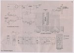
I have a CD4059 divide by N counter chip
I have the data sheet and have studied it for hours but I still cant make top nor tail
of it with its Ka, Kb Kc and jam inputs
I want to use three BCD thumb wheel switches ( Hundreds , Tens and Units)
to enable me to divide an input frequency by any integer in the range of 3 to 150
which I would set up on the 3 switches
As I said , I have really tried but I just cant follow the reasoning in the data sheet
I think its probably an age thing now that I am an old bugger
Can someone please give me a diagram of how I should connect it up before I pull
out the little hair I have left
Fingers Crossed
Don
I am sorry that this isnt about a Picaxe problem but I know from the time I have been
on this forum that there are many clever people on here and maybe one of them
might be able to assist me
I have a CD4059 divide by N counter chip
I have the data sheet and have studied it for hours but I still cant make top nor tail
of it with its Ka, Kb Kc and jam inputs
I want to use three BCD thumb wheel switches ( Hundreds , Tens and Units)
to enable me to divide an input frequency by any integer in the range of 3 to 150
which I would set up on the 3 switches
As I said , I have really tried but I just cant follow the reasoning in the data sheet
I think its probably an age thing now that I am an old bugger
Can someone please give me a diagram of how I should connect it up before I pull
out the little hair I have left
Fingers Crossed
Don
")