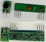
Has anyone here used the Sparkfun 434MHz RF modules with any M2 PicAxe?

...please confirm that you DO have matching pairs!? Have you -ARGH!-altered the screwed slug's position ?
According to the info on the SparkFun documents, both the transmitter and receiver PCBs match the model numbers for the 433 MHz units. As far as the screw plug's position, I haven't touched it.
 

hippy

Ex-Staff (retired)
I can't figure out how the receiver's "linear output" could appear so well-behaved while its "digital output" acts crazy.... unless this receiver itself is junk.
I would guess it's working like an AGC or automatic squelch control level on a voice radio and there will be more digital noise when the squelch signal is flat, less when it is changing.

It's like putting two 2V signals from different sources into a comparator; there will likely be a lot of switching of the output because the two 2V signals won't always be exactly the same and the slightest change in one signal but not the other causes a change of output.

The PICAXE can use the noisy signal, because the mechanisms used in the PICAXE determine that it is noise and throws it away.

As to why there are sinusoidal signals on the digital output I have no idea. It could just be normal ripple or something else. A photo / drawing of the trace might help. What frequency are these sine waves at ? How large are they ?
 

eclectic

Moderator
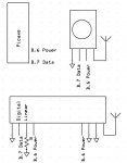
1. I had a working setup, using two AXE091 boards.
Code:
;Forum  28/09/2012
;http://www.picaxeforum.co.uk/showthread.php?22213-Has-anyone-here-used-the-Sparkfun-434MHz-RF-modules-with-any-M2-PicAxe&p=217602#post217602
;
#picaxe 28X2

;B.6 = "power" to transmitter

Main:

for b7 = 0 to 255
High B.6
pause 500
 
  RFout B.7, ("Vincero", b7)
  
  Low B.6 ; turn off power
  
  pause 250
  
  next
  
GoTo Main 
#rem
' Rx
;Pin B.6 = "power" to receiver

#picaxe 20M2

Main:

high B.6
RFin B.7, b0, b1, b2, b3, b4, b5, b6, b7
low B.6
sertxd (#b7, " ")

GoTo Main
2. Then I "found" this pair of modules in a toybox.
Swapped them into the working circuits.
Nothing!

3. Tested the two outputs with a 'scope.
Lots of "jaggies".

4. By complete fluke,
I had the receiver Digital output connected to the
Picaxe and the 'scope lead connected to the "Linear" output.
It worked!

4. Then tried a 1 MegOhm resistor on the Linear output.
Still working.

Next post for more info

e
 

Attachments

SparkFun.RX.wiring1a.jpg

SparkFun.RX.Digital.Output1a.jpg

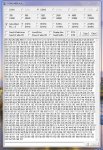
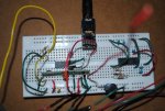
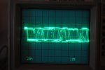
In the photo of the wiring circuit, the yellow wire is connected to the Digital Output of the receiver and provides the signal you see in the Oscope photo. The chip to the extreme right is un unrelated circuit that is not hooked up in any way. The chip you see in the "middle" of the receiver is the PicAxe, but it's not hooked up to the receiver in this photo except via the ground and power supply. The red blurry wire in the foreground is the antenna. Note that at the instant when I took the photos, the Oscope trace would "bounce" a little, so the baseline isn't where it normally is, at zero volts. The coupling to the Oscope is AC, and the signal looks the same with it in DC coupling. The Oscope photo was taken with the transmitter turned off, and no apparent signal was showing on the Linear Output. The Oscope was set to 2 volts/Div, and 0.2 msec/Div.

The square looking thing in top center is the PicAxe adapter board that communicates with the PC. Signals on the Oscope look the same with or without the PC connected.

Sorry for taking so long to get around to posting this.
 
Here's a link somebody provided to me that purportedly shows the internal wiring diagram of these type of receivers, though this one is for the 315MHz variety.

http://mbed.org/media/uploads/4180_1/315mhzrec.png

I believe CN 2 is the digital output,
CN 3 is the linear output.
CN 8 appears to be the antenna.

On my receiver, I get crappy outputs on the digital output with or without the antenna connected. And even if I ground the antenna, the digital output appears as you see in the photo above.
 
...
4. By complete fluke,
I had the receiver Digital output connected to the
Picaxe and the 'scope lead connected to the "Linear" output.
It worked!

4. Then tried a 1 MegOhm resistor on the Linear output.
Still working....
eclectic,

interesting results. I'll give that a try on my end and see what happens.

Thanks.
 
....
4. By complete fluke,
I had the receiver Digital output connected to the
Picaxe and the 'scope lead connected to the "Linear" output.
It worked!

4. Then tried a 1 MegOhm resistor on the Linear output....

Just to humour me, can you trypost #43?....
eclectic,

OMG! The noisy crap went away! WOW! Just looking at the Oscope, the signal it's picking up from the transmitter now does not look unreasonable. There's hope! I just need to hook up my PC and see if it can read the transmission. There's hope! I'll post my results in about 40 minutes....
 

hippy

Ex-Staff (retired)
4. By complete fluke,
I had the receiver Digital output connected to the Picaxe and the 'scope lead connected to the "Linear" output.
It worked!
Interesting. Most receivers seem to have two output pins, different interface circuits show connecting one, the other, and sometimes both. Sometimes the manufacturer's datasheet will show a particular connection but experimentation shows another connection is better, even necessary. We even put a comment on that in the AXE213 datasheet.

It's rare to see a circuit of a receiver in a datasheet but NoEinstein's linked-to circuit makes sense and seems likely even if not exact for all receiver modules.
 
Well, I wish I could say it's working perfectly, but I'm still not seeing anything come up on the Debug screen when I run the simple PicAxe programs I posted in #3. The signals on the digital output pin look amazingly better, though. eclectic is a genius for coming up with that one. The noise seems to have completely disappeared. And when the transmitter is turned off, the digital output signal goes thankfully flat. Maybe I missed something somewhere, but I don't remember reading any Sparkfun docs that said to ground the Linear Output pin. Strange.

A quick question: when my Debug screen pops up at the start of my program, ALL of its boxes are blank. And if I close the Debug screen and open it up again using the menu (while the RF program is running), it is still all blank. Is that normal? I would think that the other variables would be filled with zeros or something.

In any case, maybe now would be a reasonable time to try the "old fashioned" serial output methods and see if they work with this cleaned-up output.

Thanks again!
 

hippy

Ex-Staff (retired)
A quick question: when my Debug screen pops up at the start of my program, ALL of its boxes are blank... Is that normal?
And does it show "Debug - (waiting...)" in the title bar ? If so it's not receiving or not recognising any debug packets.
 
Please can you try
both
programs from post #43...
Yes, I'll be happy to try those. It will have to wait until later tonight, though. Thanks.


And does it show "Debug - (waiting...)" in the title bar ? If so it's not receiving or not recognising any debug packets.
Yes, it shows "Debug - (waiting...)" So if the PC is not receiving any packets, what does that mean? Does that merely mean the RF link is not working or does that mean there is something else also going wrong? something wrong with my serial connection between the PicAxe and the PC? I guess I should try some basic PicAxe Debug code and see if it can spit data out to the PC.
 

eclectic

Moderator
Debug is slow.

Sertxd IMO is better for this task.

Perhaps try

Code:
#picaxe 18M2
;or whatever Picaxe you have

#terminal 4800

main:
for b0 = 0 to 255

sertxd (#b0,"  ")

pause 500

next


goto main
 
... I guess I should try some basic PicAxe Debug code and see if it can spit data out to the PC.
I tried a super simple program just to see if my PicAxe could indeed send data back to the PC via Debug, and at least that part seems to be working. Later tonight I will tackle the receiver problem again and try your other suggestions. :)
 
UPDATE:
EDIT:NOTE: See post #62 below for an update of my lessons learned on this.


Success! I did NOT use the RFin and RFout commands but instead used the "old-fashioned" serin and serout commands as per russbow's code (Post #4). Also, of course, I used eclectic's idea (Post #43) of grounding the receiver's "Linear Output" pin via a resistor (in my case a 200K resistor), which turned out to be absolutely essential.

At a distance of 10 meters between receiver and transmitter, I'm getting at least 90% accuracy on the transmission, which is good enough for my purposes. At a distance of only 2 meters, that accuracy drops down to about 70-80%.

Thanks to all of you for helping me out with this. I'm posting the code in case anyone is interested.

This is the transmitter code I used for testing purposes...
Code:
;Serial.TX.Test1a
;29 SEPT 2012

;This program uses the old fashioned method for transmitting
;bytes on a cheap TX.

Main:

b0=b0+1

High B.1
SerOut B.1,T600_4, ("UUUUUUUUUUUUU") 'Wake up Rx.
Pause 5
SerOut B.1,T600_4,($AA, $BB, $CC, b0) 'Output data.
Low B.1

IF b0>225 THEN
  b0=0
  END IF

GoTo Main
This is the code I used for the receiver...
Code:
;Serial.RX.Test1a
;29 SEPT 2012

;This program uses the old fashioned method for receiving
;bytes on a cheap RX.  It outputs to the PC terminal.

;Start the PC terminal...
sertxd ("Start", CR,LF)
pause 1000
sertxd ("Start", CR,LF)
pause 1000


Main:

Serin C.0,T600_4,( $AA, $BB, $CC ),b0
pause 5
Serin C.0,T600_4,( $AA, $BB, $CC ),b1
pause 5
Serin C.0,T600_4,( $AA, $BB, $CC ),b2
pause 5
Serin C.0,T600_4,( $AA, $BB, $CC ),b3
pause 5
Serin C.0,T600_4,( $AA, $BB, $CC ),b4
pause 5
Serin C.0,T600_4,( $AA, $BB, $CC ),b5
pause 5
Serin C.0,T600_4,( $AA, $BB, $CC ),b6
pause 5
Serin C.0,T600_4,( $AA, $BB, $CC ),b7
pause 5

;View variables on the PC terminal...
sertxd (#b0," ",#b1," ",#b2," ",#b3," ",#b4," ",#b5," ",#b6," ",#b7,CR,LF)


GoTo Main
Thanks everyone! :)
 
Last edited:

manuka

Senior Member
Great- & glad you've slowed the data rate - try even slower (300bps). That 90% at 10 metres is only a modest success in my books! You still REALLY need to monitor your local 433 MHz RF environment. This is usually essential when wireless woes development-perhaps Monday morning with the return of a nearby commercial firm's wireless doorbells/coffee machine/security system...

"T" (true) serial idles high & is often wasteful of the TX battery. "N" ( inverted) idles low & is more energy efficient. Stan.
 
... That 90% at 10 metres is only a modest success in my books! ...
Well, it's something better than 90% but I'm not sure how good it is. And nothing I build ever works 100%. :) Besides, after all the headaches I went through with this particular receiver, I'm very happy I got it to work at all.


... You still REALLY need to monitor your local 433 MHz RF environment. ...
Yes, I plan to do that just for fun, and I plan to do that with your suggested system. It looks cool.

"T" (true) serial idles high & is often wasteful of the TX battery. "N" ( inverted) idles low & is more energy efficient. Stan.
That's very interesting. I will eventually need to worry about battery consumption on the receiver end, so I'll have to try that out.

Thanks for your patience and all the great advice you've provided. :)
 
Quite by accident, I discovered today that these Sparkfun units work better without the antennae than with them, at least at a distance of 4 meters or so. In fact I was able to get them to work with the PicAxe rfin and rfout functions with no problem. The code I posted in this thread at #3 now works like a charm.

I suppose these units are tuned without antennae, so at relatively close range, I guess it's best to run without them. However, I haven't tested them at a larger distance.
 

eclectic

Moderator
Quite by accident, I discovered today that these Sparkfun units work better without the antennae than with them, at least at a distance of 4 meters or so. In fact I was able to get them to work with the PicAxe rfin and rfout functions with no problem. The code I posted in this thread at #3 now works like a charm.

I suppose these units are tuned without antennae, so at relatively close range, I guess it's best to run without them. However, I haven't tested them at a larger distance.
What was the circuit?
Or, did you ground one of the outputs?

e
 
What was the circuit?
Or, did you ground one of the outputs?

e
I grounded the Linear Output pin via a 200K resistor, as per your suggestion, which stabilized the reception. That was a life-saver. The only other thing different is that I left off the antennae on both the receiver and the transmitter and found that I got virtually 100% reception with the rfin and rfout functions. The code I had posted in #3 now works perfectly. Even the Debug function is working as it should. I'm embarrassed to say that it never occurred to me to try running these without the "optional" antennae. It blows my mind.
 

manuka

Senior Member
No magic - I suspect (-sigh - yet again) that it's because you have high local noise at 433 MHz & drastic antenna removal simply reduces it's pickup. That high value R is probably acting as a squelch & simply bleeding off some of this rubbish to ground, giving you hence a quieter RF floor for your strong nearby signals.

SIGH- I must have stressed this a zillion times - MONITOR THE LOCAL 433 MHZ CONDITIONS (or head out to a quiet area) IF PROBLEMS OCCUR !!! You may well have a powerful signal next door that's swamping your own flea power transmitter. Where exactly are you anyway? Urban/rural?

A scientific approach to investigate this quirk should be followed anyway. First remove just the transmitter's antenna,next remove the receiver's antenna (& reinsert the transmitter's),then remove both. Finally re-insert both antenna. Check the performance at each stage of course & let us know how things shape up. Stan.
 

srnet

Senior Member
SIGH- I must have stressed this a zillion times - MONITOR THE LOCAL 433 MHZ CONDITIONS (or head out to a quiet area) IF PROBLEMS OCCUR !!! You may well have a powerful signal next door that's swamping your own flea power transmitter. Where exactly are you anyway? Urban/rural?
I will repeat it for for you.

These generic modules are on a fairly restricted number of frequencies, so its almost inevitable these days that someone nearby has a device on a matching frequency.

If I am suspicious of interference, I take the kit into the middle of the local park, where I can be sure (?) I am at least 200M away from strong interference, sometimes even that has not been enough.
 

manuka

Senior Member
nearby has a device on a matching frequency
srnet: It gets worse! Most cheapie 433 MHz ASK receivers,although quite sensitive,are NOT selective. Their broad response,arising from the ISM band being ~1.7MHz wide,means they'll typically pick up anything strong that's near a nominal 433.920 MHz.
 
...
....MONITOR THE LOCAL 433 MHZ CONDITIONS (or head out to a quiet area) IF PROBLEMS OCCUR !!! ....
Hi Stan and srnet,

Yes, Stan, your monitoring device is on my to-do list (I have a question concerning this at the bottom of this post :) ). I live in a rural area, so my nearest electronics supply store is well over an hour away, so I generally build up a critical mass of "parts needed" before I place a mail order.

Here was one result of my scientific troubleshooting approach:
The receiver was placed on the metal roof of a small building where it will eventually end up living for this project. Inside the building, about 3 meters away, I had the transmitter. Both had an antenna at first, and both were using the "old-fashioned" serin and serout software approach. The transmissions were working at about 70% reliability under those conditions, which is good enough for my purposes.
Next, I removed the transmitter's antenna. I noticed the reliability of the transmissions jumped up to nearly 100%. I suppose if neighborhood RF interference were the original culprit, then removing the transmitter's antenna would have not helped much.
After that, I removed the receiver's antenna, and the reliability remained nearly 100%, if not perfect. However, I did notice that reliability would drop down to maybe 70-80% if I oriented the receiver in certain ways, so there appears to be a directional dependency here of some sort.
After testing on the roof, I brought both the receiver and the transmitter back inside my house and separated them by about 4 meters. I left off the antennae on both units and noticed reception reliability remained very high, probably 100%. So I reloaded my old software (posted in entry #3) and tried again with the rfin and rfout commands, and the system worked perfectly.
From this I concluded RF interference is probably not the largest of my problems, but something about the use of antennae might be. In any case, the system appears to be working.

Eventually, this project might find its way into urban areas where there is, indeed, lots of RF interference, so I was wondering what would be the general approach for reducing noise like that with a cheap RF system such as this? If you need the reliability of something like a garage door opener, would an encoded 8-byte message be good enough if the reliability of transmission were only, say, a mere 10% but the transmission cycled over and over for a few seconds or more?

Thanks again for your insights. :)
 

jedynakiewicz

Senior Member
At the risk of complicating the matter further, perhaps those with significant RF experience may comment on the idea of placing parabolic reflectors upon the antennae. That way, the transmission would be strengthened directionally and the receiving antenna might be shielded to some extent from other RF sources; providing of course that it is not pointing directly towards an actual source of interference. If the transmitter and receiver are to be located in fixed positions this may be a way of improving matters.
 

manuka

Senior Member
NoEinstein: Good work - it increasingly still looks as if the sensitive super-regen. receiver is being overloaded. Can you try some decent spacing - say 100 yards/metres ? Rural areas may NOT be interference free - electric fences are well known culprits. ASK modulation is always going to be impulse noise prone, which is why FM devices arose (costing somewhat more).

I now avoid any such UHF data modules with visible coils & tuning caps., as they're too easily mis-adjusted, & hence DO NOT recommend these now seriously dated (late 1990s vintage) Sparkfun units for demanding work. They're great "get you started" units, but far superior offerings using near laughably simple "RF in- data out" RF ICs (Synoxo etc) abound at the same prices-or less. Typical are Dorji ASK modules, & I could send you a couple BUT 433 MHz is NOT a US legal frequency & I'd be effectively aiding and abetting. You REALLY should concentrate on 315 MHz or 900 MHz.

VERY decent & versatile data transceiver gear is now available in the US$20 range. This often uses SiLabs or Analog Devices smart RF ICs, along with superior GFSK (Gaussian Freq. Shift Keying) modulation. Ranges to km are possible, but be alert that some offerings are rather too smart for themselves & can be hard to program !

jedynakiewicz: All manner of UHF antenna designs exist,with Yagi particularly easy to make. However forget parabolic reflectors,as they need to be at least a couple of wavelengths across and are NOT viable at 433 MHz. Wavelengths there are ~70cm, so dishes are really hence too large to be feasible. Transmit antenna are usually banned anyway on 433 MHz...
 

Attachments

Last edited:
...Can you try some decent spacing - say 100 yards/metres ?....You REALLY should concentrate on 315 MHz or 900 MHz......
Thanks again, Stan. Yes, I'll eventually get around to seeing how far these units will transmit. I'll probably try a couple of 315 MHz, too, just to see if I notice much difference. For now, thanks to your help and that of others here, I've got something running that will work for my project. I've learned a lot... or "heaps" as you say.
 

saunj

Senior Member
These are working for me. The transmitter uses a 08M, the receiver a 14M2. It's for a smoke detector in an RV. The transmitter is switched on just before sending the code, idle low at 2400 baud. I send a 20 ms high, then a 10 ms low before the code. The receiver has an integrator with 20 ms time-constant to an interrupt, so the serial in is not subject to noise when the transmitter is off. I use a qualifier on serin to avoid other sources.
 
Top