Hardware Not Found Error

Codesmith

New Member
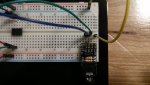
Alright it's time for a newbie question. I'm working on my first board (08M2), and I keep getting the classic "Hardware not found on COM #".

I'm using the AXE027 cable with the AXE029 adapter kit. (I've got the IN wired to C.5 [serial in], jumper set to 01, and the 01 wired to C.0. GND is connected to -)
I've gone through the troubleshooting to determine that I'm using the proper COM port (device manager + scan for USB under COM tools).
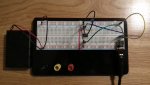
I've done the troubleshooting where you test the IN against the V0, by wiring it to a LED (and 330ohm resistor), and it behaves as normal (LED lights up when it should, and turns off when it shouldn't)

So where do I go from here? If needed I can post a video of the above, just to make sure everything is doing what I think it is, as well as piecing together the board so I know it's correct as well (it doesn't take but a minute).
 
Try 'jump starting' the program. Disconnect the power supply to the module. When you click on the download programme icon on the programme editor, as the first few bars start going across the top of the 'downloading data' box, reconnect the power/battery pack.
 

Codesmith

New Member
Alright, status update:

I don't know if it matters but for some reason energizer's AA rechargeable batteries are labeled as 1.2v, would that cause this problem on the hello world tutorial (blinking LED)?
Occasionally it will give me the "Memory Verification Failed" error, always at byte 511..
 
Same as the first suggestion, but instead of disconnecting the power unplug the jack and quickly plug it back in as the downloading starts.
 

srnet

Senior Member
I don't know if it matters but for some reason energizer's AA rechargeable batteries are labeled as 1.2v
Labelled as 1.2V because they probably are 1.2V, most AA rechargeables (NiMh) are this voltage


would that cause this problem on the hello world tutorial (blinking LED)?
Occasionally it will give me the "Memory Verification Failed" error, always at byte 511.
Quite possibly, but you need to say how many "energizer's AA rechargeable batteries" you are using.
 

Codesmith

New Member
I'm using the standard 3. When I get the chance, I'll throw 4 at it. (1.2 * 4 = 4.8v, right between the 4.5v-5v range)

If that doesn't work, I'll post a video (with time labels), showing the circuit assembly (it's a little difficult to figure out, all I've got is 6" jumper cables), final circuit, and compiling / downloading.
 

Codesmith

New Member
Alright, I've taken two pictures. The second close-up is of the axe029 and how I've got it wired. As usual, if you need anything don't hesitate to ask..

Rule of thumb:

Black -> 0V (Ground)
Yellow -> 0V (Ground) (I ran out of black...)
Red -> +V
Green -> Serial Input
Blue -> Serial Output
 

Attachments

Last edited:

Codesmith

New Member
Alright I got it, I'm just not 100% sure why, so feel free to correct me..

The way I had C.0 wired was designed to split it between the LED and SerOut. However the way I did it made the LED was the path of least resistance (Resistor > LED or SerOut), so instead I wired it to go Resistor > LED > SerOut, and it worked great.


Never mind I spoke too soon.. after trying to download it again, it doesn't appear to work...
 

westaust55

Moderator
What jonnymelon is trying to describe is the "Hard Reset" procedure which is described in PICAXE manual 1 page 50
(http://www.picaxe.com/docs/picaxe_manual1.pdf)
alternatives there is also a description in the Rev Ed PICAXE website FAQ here: http://www.picaxe.com/FAQs/Fault-Finding/


Program download errors are often associated with a supply low voltage.
Try using three normal (non-rechargeable) 1.5V Energiser cells or four 1.2 V rechargeables.

Try removing the LED from pin C.0 / SerialOut pin. The photos are a bit fuzzy however the resistor appears to be a lower value.
The LED could be pulling the SerialOut pin down and the PC is not seeing the feedback form the PICAXE during programming and thus reports a problem.
 

Codesmith

New Member
Alright, I've done some troubleshooting, and I think that the issue is the axe029 that I'm using for the serial input..

1) I'm not the only person having this issue, and across several builds, by several people, only two things are the same : AXE029 & Connection Issues
2) It appears that unless the axe029 is held in a certain position, it won't work.
3) If I hold the SerIn, SerOut, and Gnd jumpers directly to the output wire, then I get a ~100% success rate.

So, what do you think? If you agree with me, then what else can I use for a permanent solution to downloading via axe027 USB cable?
 

Codesmith

New Member
Yes I have, and it still refuses to work (even with 4 rechargeable AA batteries (all of mine seem to be 1.2v))

It also appears to only work when plugged in via USB (although I've read that this could be a ground issue, which I suspect lies once again in the axe029)
 

marks

Senior Member
Hi Codesmith ,
you dont appear to have any de-couplin caps in your circuit.
try adding a 0.1uf and 100uF close to the picaxe supply pins.
 

Codesmith

New Member
I'm not sure that I follow, where do you want the capacitors wired? (a basic circuit / picture / etc. would be great, I'm obviously new to this..)
 

SAborn

Senior Member
where do you want the capacitors wired?
As close to the picaxe as you can with the capacitor legs across the 5v+ and Gnd, its to decouple the power supply wires, all picaxe circuits should have this cap included.
 

SAborn

Senior Member
Are you sure the power 5v+ and Gnd pins on the bread board actuall go the full length of the rows on the bread board, as i have seen many bread boards where the power rows only go halfway, if this is the case it would mean you dont have a ground supply to the programming adapter board.

I dont know your bread board so its only a suggestion that you check it with a meter.
 

westaust55

Moderator
The AXE029 should not be the cause of problems.
Where some folks have had problems is trying to plug just the stereo/programming socket directly into the breadboard.if the breadboard contacts are weak it might be necessary to "align" the pins for good contact otherwise aim for pins vertical relative to the breadboard.
 
Last edited:

srnet

Senior Member
Yes I have, and it still refuses to work (even with 4 rechargeable AA batteries (all of mine seem to be 1.2v))

It also appears to only work when plugged in via USB (although I've read that this could be a ground issue, which I suspect lies once again in the axe029)
I cant make sense of that, you say it refuses to work, then that it does work ?

A lot of breadboards of the type you are using have the two power rail connection strips at the board edge, split in the middle, so the gnd strip at one end of the board is not connected to the gnd strip at that other.

When in doubt get out a meter and actually check. Are all the parts of the circuit that should be connected to 0v, +V, etc actually connected ? Do not just assume they are.
 

Technical

Technical Support
Staff member
The AXE029 will work fine and reliably if correctly assembled and inserted.

This statement
It also appears to only work when plugged in via USB
plus a look at the photos leads us to believe you may have a bad solder joint on the left hand side (as shown in the photos) of the 10k resistor on the AXE029. Resolder that joint.
 

Codesmith

New Member
After re-soldering the joint, nothing has changed, the board only works when bent slightly, and the LED only works when the board is bent. (Otherwise it blinks once per second, but my code would make it on for two, and off for two..)
 

Codesmith

New Member
On the axe029 the joints look solid, so I may just order another, as I don't have the proper materials to truly de-solder a joint.. (they're pretty cheap, and I've got things I need to order anyway)
 
Last edited:

eclectic

Moderator
On the axe029 of the joints look solid, so I may just order another, as I don't have the proper materials to truly de-solder a joint.. (they're pretty cheap, and I've got things I need to order anyway)
And, while you're there, perhaps order
de-soldering braid and a de-soldering pump. :)

Both cheap, and potentially valuable.

e
 

westaust55

Moderator
On the axe029 the joints look solid, so I may just order another, as I don't have the proper materials to truly de-solder a joint.. (they're pretty cheap, and I've got things I need to order anyway)
Do you have a multimeter (DMM) to test circuits for continuity?


After re-soldering the joint, nothing has changed, the board only works when bent slightly, and the LED only works when the board is bent. (Otherwise it blinks once per second, but my code would make it on for two, and off for two..)
If the connection from the AXE029 to PICAXE chip SERIALIN pin is intermittant, then the PICAXE will be trying to download a new program whenever it senses the SERIALIN pin float/go to a high state. That may give you the pulses on the PICAXE SERIALOUT pin which you are seeing while the PICAXE attempts to communicate back to the PC via the AXE029 board and AXE027 cable.

I recommend that you leave the LED off the SERIALOUT pin (use another such as C.1) until you get the program download and operation sorted out. What is the value of the resistor in series with the LED?
 

westaust55

Moderator
The way I had C.0 wired was designed to split it between the LED and SerOut. However the way I did it made the LED was the path of least resistance (Resistor > LED or SerOut), so instead I wired it to go Resistor > LED > SerOut, and it worked great.
reading back, this has me somewhat unclear as to exactly how you had the components wired.

Resistor > LED > SerOut for the LED circuit makes sense, but
Resistor > LED or SerOut is confusing.
A sketch of the circuit as you had it would be better.
Have you by perchance had the LED wired directly between the PICAXE SERIALOUT pin and ground bypassing the resistor?
That would overload the PICAXE output pin and damage the PICAXE chip.
 

Codesmith

New Member
No I was saying that I had wired SerOut to the same pin as the resistor and LED, instead of putting it in a 'linear' fashion after the LED.

As for a multimeter, I'm working on it, a friend had to borrow mine, leaving me to look for another that I have lying around..
 
Top