My computer won't detect my Picaxe. I enabled the serial port, chose the right COM number, and when I apply power to my Picaxe 18X and hit run, it gets stuck on finding the picaxe and then an error message pops up saying that it will not run. I have tried the Serial Tester and I get 5.5v at the input pin when the LED is off and -.5 when it's on. I have checked and double checked and my power supply and circuit are both good. What is wrong?
Hardware not detected
- Thread starter fizzit
- Start date
Andrew Cowan
Senior Member
Can you confim the 10K resistor is between the download socket and ground, and not on the wrong side of the resistor?
What is the voltage between pins 5 and 14?
A
What is the voltage between pins 5 and 14?
A
hippy
Ex-Staff (retired)
Welcome to the PICAXE forum.
There are a wide range of reasons why the PICAXE might not respond. It appears that your cable is connected and working so it more likely has something to do with the external hardware.
What hardware are you using - Is it on bread-board, your own design or a Rev-Ed PCB ?
What happens when you click the Firmware button ( View->Options->Mode ) ?
Have you ever been able to succesfully download with your setup ?
One thing worth trying is to initiate a download, wait for the "Connecting to hardware..." message to appear then power on your PICAXE - This is what's called a Hard Reset procedure which can often fix things.
BeanieBots
Moderator
In addition to everything mentioned by Hippy,
what logic level is your reset pin at?
what logic level is your reset pin at?
5 volts. The 10K is between download in and ground. I have never successfully downloaded, my chip is new and this is my first try at programming it. Reset is tied to high with a 4k7. I will attempt the hard reset procedure.Can you confim the 10K resistor is between the download socket and ground, and not on the wrong side of the resistor?
What is the voltage between pins 5 and 14?
A
Edit: I'm on a breadboard.
Last edited:
OK, I did it, it didn't work. How would I be able to check if the picaxe chip is in working condition? I went into serial port settings and set the baud rate to 4800.5 volts. The 10K is between download in and ground. I have never successfully downloaded, my chip is new and this is my first try at programming it. Reset is tied to high with a 4k7. I will attempt the hard reset procedure.
This is probably the most frustrating stage of getting a picaxe working. There are so few clues as to why it won't work. Once you do get it working, it is very hard to stop it, so let's persevere.
It could be invalid voltage levels on the RS232 port. Can you put the ground lead of the multimeter on the ground of the circuit and measure the volts where the 10k and 22k resistors join. You should get somewhere between minus 9 and minus 12V. Then try a download and it should briefly go positive.
It could be invalid voltage levels on the RS232 port. Can you put the ground lead of the multimeter on the ground of the circuit and measure the volts where the 10k and 22k resistors join. You should get somewhere between minus 9 and minus 12V. Then try a download and it should briefly go positive.
>> "The 10K is between download in and ground."
Just to make sure, you mean the download connector and ground, correct? (i.e. not the Picaxe's download pin). In other words: 10 kOhm between download connector and ground. 22 kOhm between the 10 kOhm resistor (non-grounded end!) and the Picaxe input.
Second, could you make one or more photo of your setup from different angles? (even a cellphone camera one is better than nothing) - that way all people on the forum can help with visual debug. It may be something obvious once we can see it.
Wolfgang
BeanieBots
Moderator
As pointed out by Womai, your description of the connection is still vague. A picture would clear things up.
Dumb question, but is it a PICAXE or a blank 16F88 PIC?
Where did you get it from?
The PE programming baud rate cannot be changed. It's fixed except by use use of the clock frequency setting. What exactly have you changed?
What happens if you do a 'firmware?' check?
Is there any other "history" that we should know about?
Such as; have you ever connected it to maybe an unsuitable power supply?
SilentScreamer
Senior Member
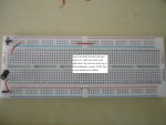
Might be stupid (I've done it more than once  ) but are you using your breadboard correctly? Look at the attachment.
As already said can you post a photo so we can see your breadboard
) but are you using your breadboard correctly? Look at the attachment.As already said can you post a photo so we can see your breadboard
Attachments
-
 252 KB Views: 72
That's seems a bit of a confusing photo....
I've got several of those generic breadboards and they dont need links in them halfway down the supply rails. (EDIT: but I've just noticed that mine have got continous silk screen lines, but yours have breaks in the middle indicating that a link may be required)
I always thought that the convention was that the blue and red lines down the supply rails were for +V and 0V, allowing you to have both rails on both sides ... having plus and minus on different sides is a new one on me (but my breadboards came with no instructions so I could be wrong)
...and you've got the +V rail next to the blue stripe and the 0V rail next to the red stripe - that would lead me to letting out magic smoke a few times....
I've got several of those generic breadboards and they dont need links in them halfway down the supply rails. (EDIT: but I've just noticed that mine have got continous silk screen lines, but yours have breaks in the middle indicating that a link may be required)
I always thought that the convention was that the blue and red lines down the supply rails were for +V and 0V, allowing you to have both rails on both sides ... having plus and minus on different sides is a new one on me (but my breadboards came with no instructions so I could be wrong
)...and you've got the +V rail next to the blue stripe and the 0V rail next to the red stripe - that would lead me to letting out magic smoke a few times....
Last edited:
SilentScreamer
Senior Member
I've always been taught +V across the top, 0V across the bottom. I thought the break was so multiple +V values could be used (i.e. 3.3V and 5V).That's seems a bit of a confusing photo....
I've got several of those generic breadboards and they dont need links in them halfway down the supply rails.
I always thought that the convention was that the blue and red lines down the supply rails were for +V and 0V, allowing you to have both rails on both sides ... having plus and minus on different sides is a new one on me (but my breadboards came with no instructions so I could be wrong
hippy
Ex-Staff (retired)
Different manufacturers use different schemes for connecting the separate blocks of holes. Sometimes they are individual, disconnected islands, sometimes completely joined, sometimes some are joined but separated into groups of blocks. Where the board is silk screened as in the photo I'd expect the tracks to be contiguous across blocks execpt where the silk screened lines breaks.
To avoid any doubt, accidents, tears and expense - always check with a continuity meter to determine how they are wired rather than make assumptions.
To avoid any doubt, accidents, tears and expense - always check with a continuity meter to determine how they are wired rather than make assumptions.
Andrew Cowan
Senior Member
The large breadboards that I use have a break in the silk screen, and require a wire to connect the two halves.
A
A
@Dr_Acula: Yeah, that works fine for me. The voltages are as they should be.
@womai: Yes, I meant the download in on the jack.
I changed the baud rate by going into windows hardware devices management and opening the COM1 settings. I have used my breadboard plenty and I know how it works. My picaxe is from Sparkfun, and it is defenitely an 18X. I'll try to get a picture on very soon. Firmware gives the same thing. My powersupply goes up to 3A and I've got it on 5v, max current (as in, it doesn't limit the current supplied). I am worried that I might have hurt my chip somehow, I don't remember doing it but I could have somehow messed it up. I'm nearly positive my circuit is perfect. Any pin voltages or anything I can check to see if the picaxe isn't fried?
Have you tried a Firmware check as suggested?
I built a new prototype this week and I could read the firmware but not program the chip. Very confusing
Turned out that I hadn't connected the download circuit ground to the picaxe ground. Which is embarassing to post here, but could be a useful point for others...
...and weird that it did what it did. I suspect the extra current needed to program the picaxe (which I read somewhere IIRC) over just asking it to report back an internal firmware version caused grounding problems.
Can you confirm exactly what you are seeing in the error message. There is no message that I know of that says something "will not run"......and when I apply power to my Picaxe 18X and hit run, it gets stuck on finding the picaxe and then an error message pops up saying that it will not run....
slimplynth
Senior Member
I put my home made 20M board into a project box the other day, prior to this it downloaded 100% of the time.
Now it may be more like 1 in 3 attempts... i'm not sure if its anything to do with it but if I go to options in the PE and do a firmware check it seems to enable the next program download (seems to be).
The other time I had a download stall (timeout) was while I was converting a large AVI file to DVD in the background... that gave a small serial port error message ending 0X00some numbers..
Why you need a dedicated cheap PC for PICAXE ;-)
John
Not an unexpected event - video processing is both processor-intensive and time-critical: the serial port didn't have a high enough priority to interrupt it, so the serial communications timed out.The other time I had a download stall (timeout) was while I was converting a large AVI file to DVD in the background... that gave a small serial port error message ending 0X00some numbers..
John
slimplynth
Senior Member
yeah, cheers john - i guessed that was the cause but didn't know the exact reason, thanks.
lee
lee
inglewoodpete
Senior Member
@Fizzit,
I think you need to go back to basics. Have you sucessfully programmed any PICAXE with your PC?
18Xs can be a little difficult to program at times. Try running it on 3 x AA cells - just to program it.
Also, connect a LED + 330ohm resistor between the Serial Out pin (leg 2) and 0v. Does the LED flicker when you attempt to communicate (download or check firmware) with the PICAXE?
Nope. This is my first Picaxe with my PC. I am using the serial cable and I have confirmed it works using the built in connection tester in the programming environment. The firmware check does not work and returns the same result.@Fizzit,
I think you need to go back to basics. Have you sucessfully programmed any PICAXE with your PC?
18Xs can be a little difficult to program at times. Try running it on 3 x AA cells - just to program it.
Also, connect a LED + 330ohm resistor between the Serial Out pin (leg 2) and 0v. Does the LED flicker when you attempt to communicate (download or check firmware) with the PICAXE?
BeanieBots
Moderator
That'll be some background software you have.
Many things such a PDAs, interactive white boards and some mobile phone software continually check the ports for attached hardware.
Start your PC in safe mode and see if it stops happening.
Many things such a PDAs, interactive white boards and some mobile phone software continually check the ports for attached hardware.
Start your PC in safe mode and see if it stops happening.
hippy
Ex-Staff (retired)
Going back to the first post, something I hadn't spotted at the time ...
Exactly what serial download cable are you using ? Physical COM port or USB ? If USB, is it a genuine Rev-Ed AXE027 or USB010 or something else ?
The voltage readings appear to be reversed to what would be expected.I have tried the Serial Tester and I get 5.5v at the input pin when the LED is off and -.5 when it's on.
Exactly what serial download cable are you using ? Physical COM port or USB ? If USB, is it a genuine Rev-Ed AXE027 or USB010 or something else ?
This is Serial Out from the PICAXE ? That would seem to fit with the serial cable providing the wrong voltage levels.I checked the Serial Out pin with the LED setup you specified and every few seconds it flashes.
monkeydust
New Member
Hello there.
I'm sorry to hijack this thread, but I'm also having the dreaded "Hardware not Detected".
This is on two different computers.
Please can you take a look at my download circuit and tell me if I've done something stupid?
www.myox.co.uk/board1.jpg
www.myox.co.uk/board2.jpg
Thanks, David
I'm sorry to hijack this thread, but I'm also having the dreaded "Hardware not Detected".
This is on two different computers.
Please can you take a look at my download circuit and tell me if I've done something stupid?
www.myox.co.uk/board1.jpg
www.myox.co.uk/board2.jpg
Thanks, David
BeanieBots
Moderator
That diode in series between supply and Vcc pin won't help.
(with no decoupling cap either, it's just asking for trouble)
Use a 4.5v supply such as 3 X AA batteries with no diode.
(with no decoupling cap either, it's just asking for trouble)
Use a 4.5v supply such as 3 X AA batteries with no diode.
monkeydust
New Member
Thanks for the quick reply, BeanieBots.
I originally had decoupling caps in, but took them out as I thought (wrongly) they may have been causing the problem.
I've rejigged it with 3 x AA, no diode - still not working.
I'm testing it by clicking the "Firmware" button, which should respond ok if the link is right?
I originally had decoupling caps in, but took them out as I thought (wrongly) they may have been causing the problem.
I've rejigged it with 3 x AA, no diode - still not working.
I'm testing it by clicking the "Firmware" button, which should respond ok if the link is right?
hippy
Ex-Staff (retired)
A few things -
It's not clear to me what colours / value the reset pull-up is. 4K7 is the usually recommended value but isn't too critical. If it's not 4K7, replacing it with 4K7 gets one possible problem ticked off the list.
Jack sockets can sometime have poor mating contact with breadboard. It may be worth soldering some flying leads to the jack socket pins rather then insert the socket into the breadboard. There's also the AXE029 breadboard adapter which can be used for this job.
If there are two pins on each side of the socket; make sure you get the right ones or link both of each pair together.
Not sure if you have the outer sets of contacts for the jack crossed-over. For the standard Rev-Ed socket (CON039), viewed from above inlet to bottom ( as in your picture ), left side is serial in, right side is 0V. The Serial Test should help identify if that's wrong - disconnect both leads from the breadboard, run the serial test, turn the on-screen LED on and off, which ever wire toggles high-low goes to Serial In via the 10K/22K.
monkeydust
New Member
Hippy - as usual you're a lifesaver - thanks!
Soldering leads onto the jack solved the problem.
You were right, I'd also hooked it up with left
and right cables switched! d'oh.
David
Soldering leads onto the jack solved the problem.
You were right, I'd also hooked it up with left
and right cables switched! d'oh.
David
A few things -
It's not clear to me what colours / value the reset pull-up is. 4K7 is the usually recommended value but isn't too critical. If it's not 4K7, replacing it with 4K7 gets one possible problem ticked off the list.
Jack sockets can sometime have poor mating contact with breadboard. It may be worth soldering some flying leads to the jack socket pins rather then insert the socket into the breadboard. There's also the AXE029 breadboard adapter which can be used for this job.
If there are two pins on each side of the socket; make sure you get the right ones or link both of each pair together.
Not sure if you have the outer sets of contacts for the jack crossed-over. For the standard Rev-Ed socket (CON039), viewed from above inlet to bottom ( as in your picture ), left side is serial in, right side is 0V. The Serial Test should help identify if that's wrong - disconnect both leads from the breadboard, run the serial test, turn the on-screen LED on and off, which ever wire toggles high-low goes to Serial In via the 10K/22K.
OK, anyways, de-hijacking the thread:
Yes, I am almost positive that my cable is genuine, I got it from sparkfun and they say it is an original Rev Ed product, same with my picaxe. It's the serial cable, not USB, and it is a true COM port. I have no software that checks the serial port (almost positive about that) and that doesn't really make sense anyways as it was Pin 2, the Picaxe serial out. How does the flashing fit with the wrong voltage levels? I thought that the flashing was the chip checking for downloads...
Should I try another computer?
OK, I just fully tested the serial connection. When I do a firmware check, it stops blinking after I click the mouse until the "not detected" dialog comes up, and then comes on dimly (I assume because it's transmitting data) for a couple seconds and flashes bright for a second and goes back to sporadically blinking. Really, really wierd.
Last edited:
hippy
Ex-Staff (retired)
The important voltage is that on leg 3 ( Serial In ). During serial test, that should be near +V when the on-screen LED is on, near 0V when the on-screen LED is off. In post #1 you say it was the reverse of that. Double-check that test.
When the PICAXE sees leg 3 high it enters the download mode and indicates that by communicating with leg 2. If leg 3 remains high, the PICAXE timesout, restarts, sees leg 3 is high and repeats the indication.
Seeing repeating activity on leg 2 suggests that leg 3 is permanently high. That would be the case as described in post #1 where leg 3 is said to be near +V when the on-screen LED is off.
Yes, it would be worth testing on another computer
Great! Thanks. I will try it on another computer this evening. I wonder why right when the dialog came up the LED stayed on for a couple of seconds instead of still flashing.The important voltage is that on leg 3 ( Serial In ). During serial test, that should be near +V when the on-screen LED is on, near 0V when the on-screen LED is off. In post #1 you say it was the reverse of that. Double-check that test.
When the PICAXE sees leg 3 high it enters the download mode and indicates that by communicating with leg 2. If leg 3 remains high, the PICAXE timesout, restarts, sees leg 3 is high and repeats the indication.
Seeing repeating activity on leg 2 suggests that leg 3 is permanently high. That would be the case as described in post #1 where leg 3 is said to be near +V when the on-screen LED is off.
Yes, it would be worth testing on another computer
GAAAAAAAAAAAAAAAAAAAAAAAHHHHHHHHHHHHHHHHHHHHH!!!!!!!!
OK. Sorry. Needed to get that out.
I tested it on my other computer, and I still can't program it. The LED I installed on the Serial Out pin (of the picaxe) tests out good with the Serial Tester when I first plug it in and give it power, but after a few seconds it stops and I have to unplug the serial cable from the picaxe and disconnect the power and restart to get it to work again. When I try to download, the LED stays on for about 5 seconds while it's trying to connect and then turns off most of the time and after that it's off for a couple seconds and the the dialog comes up. Please help!
The LED on serout should be permanently off unless a download is in process.
So you definately have a hardware problem somewhere. Posting a photo would help.
Our guess would be either
1) the 4k7 pull up resistor on the reset pin not correctly fitted - test with a multimeter.
2) the 10k/22k on serin not correctly fitted.
So you definately have a hardware problem somewhere. Posting a photo would help.
Our guess would be either
1) the 4k7 pull up resistor on the reset pin not correctly fitted - test with a multimeter.
2) the 10k/22k on serin not correctly fitted.
similar problem with 28x1
I am trying to download to a 28x1 with the same results. I have been following this thread and have tried all the recommendations with no luck. I even added a RS232/TTL converter on serial out, even though I had already tried two different computers. I monitored serial in and serial out with an oscilliscope and can see serial in go high when I try to download and I see serial out return a pattern to the computer but the computer doesn't recognize it. I tried looking at the return pattern with Hyperterminal but without knowing the data speed and format it didn't prove too much other than that Com1 sees something coming back. Is there any way to determine what the bootloader sends back to the program to signal it is there and ready?
I am trying to download to a 28x1 with the same results. I have been following this thread and have tried all the recommendations with no luck. I even added a RS232/TTL converter on serial out, even though I had already tried two different computers. I monitored serial in and serial out with an oscilliscope and can see serial in go high when I try to download and I see serial out return a pattern to the computer but the computer doesn't recognize it. I tried looking at the return pattern with Hyperterminal but without knowing the data speed and format it didn't prove too much other than that Com1 sees something coming back. Is there any way to determine what the bootloader sends back to the program to signal it is there and ready?
inglewoodpete
Senior Member
Howie,
You say Hyperterminal recieves some data back from the PICAXE via COM1 when you try to download. That is a good sign.
I'm assuming you're using a Serial cable and port on the computer.
Take out the RS232/TTL converter and try the "Check Firmware" feature. It should work.
I have programmed 100s of PICAXEs on several PCs using serial or USB cables and rarely have failures. When it does fail, there is usually a good reason.
Finally, it is probably better to start your own thread with your problem rather than hijack someone elses, especially when theirs is still unresolved.
Peter
You say Hyperterminal recieves some data back from the PICAXE via COM1 when you try to download. That is a good sign.
I'm assuming you're using a Serial cable and port on the computer.
A RS232/TTL converter will probably invert the return data, stopping the download from working.I even added a RS232/TTL converter on serial out
Take out the RS232/TTL converter and try the "Check Firmware" feature. It should work.
I have programmed 100s of PICAXEs on several PCs using serial or USB cables and rarely have failures. When it does fail, there is usually a good reason.
Finally, it is probably better to start your own thread with your problem rather than hijack someone elses, especially when theirs is still unresolved.
Peter