westaust55
Moderator
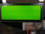
I was recently given a few 20x4 character type LCD modules by our IT group from some Equitrac systems that had been decommissioned. These 2002 vintage modules have a Hantronix HDM20416L-1-Y1ES display using a KS0066U controller chip.
See: http://www.hantronix.com/page/index/products/character
After changing out the centered header pins (that were protruding 50-50 each side of the PCB) for some that were in effect protruding fully to one side of the PCB, I soon had the displays up and running.
Having recalled that there has been some past posts about problems with the KS0066 controller chips I can advise that:
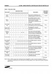
1. They use the same command set and initialization as the Hitachi HD44780 controller chips
2. The Hantronix specs (as downloaded March 2013) if followed at page 44 for Character Module Initialization will not initialise the KS0066 chips into a useable position. The reason is that the Display Clear data specifies a value of 8 whereas to turn on the display the “D” bit (bit 2) must be set so a value of $0C (decimal 12) must be sent.
3. The Samsung KS0066U datasheet (as downloaded March 2013) if followed at the page for Initialization by instruction does not include the sending of $30 and $30, $30 for 8-bit interface of $03, $03, $03, $02 for 4-bit mode. Failure to include these first bytes of data, at least for earlier (ie ~2002 manufactured) KS0066U chips will result ion failure to initialize.
There are some timing parameters that are specified for these displays which differ between the various datasheets, however with a PICAXE chip as the "driver" I found that they would initialize okay without some the specified timing delays. The timing delays are as follow:
1. 30ms (Samsung) or 20 ms /15 ms (Hantronix for 8 or 4-bit interface respectively) – I used 50 mS for good measure
2. Hantronix (but not Samsung) specify >= 4.1 ms delay after the first data Function Set byte/nibble – I removed this without incurring problems
3. Samsung (but not Hantronix) specify a >= 1.53 ms delay between display clear data and Entry Mode set data. - I removed this without incurring problems.
Omission of the Entry Mode Set data did not seem to effect the initialization/operation of the HDM20416L-1 type display (with KS0066U controller) however I have retained this in my initialsiation code.
Hopefully others who may latter purchase an LCD display using the Samsung KS0066U controller chip may find this useful.
Some demo code for the 4-bit interface mode is as follows:
See: http://www.hantronix.com/page/index/products/character
After changing out the centered header pins (that were protruding 50-50 each side of the PCB) for some that were in effect protruding fully to one side of the PCB, I soon had the displays up and running.
Having recalled that there has been some past posts about problems with the KS0066 controller chips I can advise that:
1. They use the same command set and initialization as the Hitachi HD44780 controller chips
2. The Hantronix specs (as downloaded March 2013) if followed at page 44 for Character Module Initialization will not initialise the KS0066 chips into a useable position. The reason is that the Display Clear data specifies a value of 8 whereas to turn on the display the “D” bit (bit 2) must be set so a value of $0C (decimal 12) must be sent.
3. The Samsung KS0066U datasheet (as downloaded March 2013) if followed at the page for Initialization by instruction does not include the sending of $30 and $30, $30 for 8-bit interface of $03, $03, $03, $02 for 4-bit mode. Failure to include these first bytes of data, at least for earlier (ie ~2002 manufactured) KS0066U chips will result ion failure to initialize.
There are some timing parameters that are specified for these displays which differ between the various datasheets, however with a PICAXE chip as the "driver" I found that they would initialize okay without some the specified timing delays. The timing delays are as follow:
1. 30ms (Samsung) or 20 ms /15 ms (Hantronix for 8 or 4-bit interface respectively) – I used 50 mS for good measure
2. Hantronix (but not Samsung) specify >= 4.1 ms delay after the first data Function Set byte/nibble – I removed this without incurring problems
3. Samsung (but not Hantronix) specify a >= 1.53 ms delay between display clear data and Entry Mode set data. - I removed this without incurring problems.
Omission of the Entry Mode Set data did not seem to effect the initialization/operation of the HDM20416L-1 type display (with KS0066U controller) however I have retained this in my initialsiation code.
Hopefully others who may latter purchase an LCD display using the Samsung KS0066U controller chip may find this useful.
Some demo code for the 4-bit interface mode is as follows:
Code:
'         COMMAND SUMMARY 4 BIT MODE

'( 1) Clear Display
'( 2) Cursor Home
'( 8) Display Off
'(12) Display On/Restore Cursor Off
'(128-147) Line 1 Cursor Position
'(192-211) Line 2 Cursor Position
'(148-167) Line 3 Cursor Position ~ continuation of line 1
'(212-231) Line 4 Cursor Position ~ continuation of line 2
'(13) Blinking Cursor
'(14) Underline Cursor
'(16) Move Cursor Left
'(20) Move Cursor Right
'(24) Shift Display Left
'(28) Shift Display Right

	#PICAXE 18m2
	#TERMINAL OFF

'  PICAXE IO Allocation
'            DB7  = C.3
'            DB6  = C.2
'            DB5  = C.1
'            DB4  = C.0
	SYMBOL E    = B.6
	SYMBOL RS   = B.7

' Variable Usage
	SYMBOL senddata    = b0
	SYMBOL index       = b1


 ; Initialisation from Hantronix datasheet
 '  --> (4Bit)(Function 4bit/2line/5x7)(Display = On)(Clear Display)(Entry Mode = Increment/No Disp Shift)
	EEPROM  0,($33,$32,$28,$0C,$01,$06)
	EEPROM 20, ("PICAXE 18M2+ with a ")
	EEPROM 40, ("Hantronix series LCD")
	EEPROM 60, ("HDM20416L-1-Y1ES    ")

      SETFREQ M8
 	dirsB = %11101101
 	dirsC = %00001111

Intialise:
	PAUSE 100   ; = 50 ms at 8 MHz - delay >= 30 ms by Samsung datasheet
	FOR  index = 0 to 5
                  READ index, senddata : GOSUB send ' Initialise LCD						NEXT index : PAUSE 10

Main:
      LOW RS  :senddata = 128 : GOSUB Send : HIGH RS '(128-147) Line 1 Cursor Position

  	FOR index = 20 TO 39
 	  READ index, senddata : GOSUB Send ' sending characters to line two
 	NEXT index


      LOW RS  :senddata = 192 : GOSUB Send : HIGH RS '(192-211) Line 2 Cursor Position
 	FOR index = 40 TO 59
 	  READ index, senddata : GOSUB Send ' sending characters to line one
 	NEXT index

      LOW RS  :senddata = 148 : GOSUB Send : HIGH RS '(128-147) Line 1 Cursor Position

  	FOR index = 60 TO 79
 	  READ index, senddata : GOSUB Send ' sending characters to line two
 	NEXT index

     DO : LOOP ; loop forever

Send:
	pinsC = senddata / 16 : PULSOUT E,1 :  pinsC = senddata : PULSOUT E,1
      RETURN
Last edited: