Hi forum,
I haven't posted a message for a while, being busy in raising my kid.
At work however we have a small project we are trying to mae sense of and I tought I would ask the forum. I know how people feel about giving advice for business use. I am not asking for any time intensive input, just the best advice people are willing to give.
I am trying to hack into a integrated motor-angular position sensor with onboard control electronics to try and take control of it. This system is used in a car engine.
First of all I want to make clear that I do not intend to use the motor on the engine itself. It will not go in a car or any other safety critical application. I must however try and make use of that specific motor to avoid expensive reworking.
The motor package contains a gearbox with worm gears which convert the rotor rotation into axial displacement of a shaft. An angular position sensor is also integrated into the system.
The reason I want to do this is because the system is impenetrable to me, because the communication of the motor+sensor with the outside is via CAN protocol. I would like to replace the onboard electronics with a suitable motor controller.
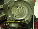
I attach the photographs of the magnetic wheel poles and the five sensors.
The sensors are labeled Z10 95E4. A search on google was less than satisfactory.
From the photographs I can see that two of the five sensors are positioned at an outer radius than the other three and that all together they should be capable to resolve the sense of rotation and the angular position. The rotor spins for several revolutions to move the shaft axially.
Can anyone help me understand how these sensors work?
Any suggestions on how to connect them together to achieve the detection of position and sense of rotation?
Does anyone know what those components (Z10 95E4 ) are?
thanks in advance
Riccardo
I haven't posted a message for a while, being busy in raising my kid.
At work however we have a small project we are trying to mae sense of and I tought I would ask the forum. I know how people feel about giving advice for business use. I am not asking for any time intensive input, just the best advice people are willing to give.
I am trying to hack into a integrated motor-angular position sensor with onboard control electronics to try and take control of it. This system is used in a car engine.
First of all I want to make clear that I do not intend to use the motor on the engine itself. It will not go in a car or any other safety critical application. I must however try and make use of that specific motor to avoid expensive reworking.
The motor package contains a gearbox with worm gears which convert the rotor rotation into axial displacement of a shaft. An angular position sensor is also integrated into the system.
The reason I want to do this is because the system is impenetrable to me, because the communication of the motor+sensor with the outside is via CAN protocol. I would like to replace the onboard electronics with a suitable motor controller.
I attach the photographs of the magnetic wheel poles and the five sensors.
The sensors are labeled Z10 95E4. A search on google was less than satisfactory.
From the photographs I can see that two of the five sensors are positioned at an outer radius than the other three and that all together they should be capable to resolve the sense of rotation and the angular position. The rotor spins for several revolutions to move the shaft axially.
Can anyone help me understand how these sensors work?
Any suggestions on how to connect them together to achieve the detection of position and sense of rotation?
Does anyone know what those components (Z10 95E4 ) are?
thanks in advance
Riccardo
Attachments
-
 107 KB Views: 53
 -
 123.3 KB Views: 55