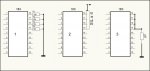
If I use a Picaxe with fixed inputs, such as the 18X or 20M,
can I connect the inputs and then ground them,via a single resistor?
As an example, an 18X which uses only Input 2 (metal leg 1).
I know that circuits 1 and 2 will work. Will circuit 3?
e.
can I connect the inputs and then ground them,via a single resistor?
As an example, an 18X which uses only Input 2 (metal leg 1).
I know that circuits 1 and 2 will work. Will circuit 3?
e.
Attachments
-
 89.7 KB Views: 58
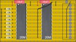
")