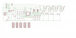
Generic Picaxe 14M board
The 14M picaxe is only $1.50 more than a picaxe 08M but has more than twice as many useful input and output pins. This project is a generic board with 4 analog inputs, 4 digital outputs driving relays, a common data bus and a header to attach to other modules. It also has spaces for radio receiver and transmitter modules.
PCBs are expensive in small quantities ($40+ each) but come down to $8 each in quantities of 10 and are even cheaper at higher quantities. So it works out cheaper to build a board with spaces for lots of components and to design a specific circuit by leaving out components.
The 14M in its standard configuration has several inputs and outputs disabled – the full configuration is described on page 70 of the Manual 1, appendix C and includes a lot more ADC inputs as well as pins that can be configured in software to be either inputs or outputs.
Features of this board:
1) A 10 pin header for power supply pins and the data bus so modules can be easily daisy chained using IDC headers and 10 wire ribbon cable.
2) Power rails for 5V, 12V and also 24VAC (or any other desired voltage). 24VAC is useful for driving power relays and sprinkler solenoids.
3) Provision for a voltage regulator for 12V to 5V. This can be omitted if 5V is available – eg from a PC power supply.
4) 4 analog inputs with divider resistors. The values shown are useful for dividing 12V inputs down to within the safe 0-5V picaxe range. If the inputs are 0-10V then the resistors can be scaled accordingly. If the inputs are always under 5V then the 1k resistors can be omitted and the 2k7 resistors replaced with wire links.
5) A data bus. There are many protocols but one problem common to many picaxes is that reading a serial data input causes the chip to hang (SERIN). Another problem is that once more than 10 devices go on a common bus then data clashes start happening. One way to get around this for each chip putting data on the bus to precede the Serout serial stream with a high pulse of a nominal time, eg 1 second. Devices looking to send data to the bus first check that the bus is low and only if it is low do they send data. Other devices listening to the bus check to see if the bus is high – if it is not high then they get on with other code. As long as the program loop checks the bus several times a second then a data packet will not be missed. Finally and to ensure that chips do not lock up with a serin, one device on the bus can be configured just to send dummy packets once a minute. This device could be an 08 or 08M (which will also fit into this board). On one only board on the bus the data bus needs to be pulled low so there is provision on this board for a 1k pulldown resistor.
6) Provision for one digital input (analog inputs can also be digital inputs as well)
7) 4 digital outputs with indicator leds and driving transistors then relays. Some or all of these can be omitted as needed.
8) Spaces for RF receiver and transmitter modules.
9) A prototyping area.
10) An area for a big 1000uF capacitor on the 12V line to absorb any voltage dips from turning relays on and off.
The main application here is for home automation – sensing light, turning on lights, turning on sprinklers, sensing tank levels and turning on pumps. It would also have applications in robotics where modules need to be added on as the project grows and some form of data bus is required.
The modules can interface with a PC – one device has the job of taking RS232 signals from a PC and turning them into the data bus protocol with a high pulse at the beginning. Another module listens to the bus for messages for the PC and sends these back to the PC via the RS232 port.
As indicated above, the board will also work with 08 and 08M chips.
Attachments
-
 140.9 KB Views: 234
 -
 210.1 KB Views: 269