FVR CalibADC10 equivilent on uM-FPU v3.1

ac246

New Member
Hi, I am trying to do some conversion of an ADC value i am reading in via the uM-FPU 3.1's built in 12 bit ADC. but to be able to ensure my figures are accurate, i need to read the internal FVR, if possible.

I am reading an oxygen sensor using the ADC and am normally reading a value of around 2600, but as i blow on the oxygen gas sensor reading goes down as expected to say there is less oxygen. this value is directly proportional to the amount of oxygen in the air.

My problem is that as the batteries run down, this ADC value is going up.. i read 2600 at a supply voltage of 5V but as the voltage is lower it gets higher. I have managed to get this to work properly using the calibADC10 command on the picaxe 40x2 which reads the internal voltage reference, but i want to be able to keep all the maths inside the FPU chip. and it also has a 12 bit adc in the fpu instead of the 10 bit on the picaxe..

Does anyone know if it is atall possible to read the internal FVR on the FPU 3.1?

Thanks

Aaron
 

srnet

Senior Member
I dont really understand the question.

The internal voltage referance is what it is, reading it makes no sense at all.
 

AllyCat

Senior Member
Hi Aaron,

I've no experience of the uM-FPUv3.1, but does it actually have a FVR? I can't see one in the data sheet that I looked at.

Even if the chip hardware does have a FVR, there don't appear to be any instructions to access it. So at best, it presumably would be necessary to "hack" some SFR data, via the PICaxe I2C comms.

I would have thought that either you need to run the FPU chip from a regulated supply rail (3.3 V?) or, if the second analogue input is not being used, then connect an external reference voltage (FVR) to the input pin and emulate the CALIBADC command in the PICaxe.

EDIT: However, I have been working on two methods to emulate CALIBADC at higher resolution (12+ bits) in a standard PICaxe. It's rather slow and you would then have to pass the value to the FPU, but it's a possibility if the PICaxe and FPU can be assumed to have an identical supply voltage.

Cheers, Alan.
 
Last edited:

oracacle

Senior Member
i think there maybe several option, start with a higher voltage regulated down, find a way to use the second ADC channel as a refrence.

however with those option a quick scan though the instruction set shows some thing else that can be handy, comands such as adcscale, i havent played with it but i suspect that it could be used to either correct the issue, or used in combinaton with a reading from the second channel to scale. it could get tricky as the scale gets applied to both channels so you may have to continuly change the scale that is used.
 

inglewoodpete

Senior Member
quick scan though the instruction set shows some thing else that can be handy, comands such as adcscale.
I think the ADCScale command would just be a multiplier to bring an ADC reading (0-255 or 0-1023 etc) to a real-world voltage like 5v or 20v FSD. You would preset the value to suit your project.

Accurate and consistent ADC readings rely on a steady fixed and smooth (noise-free) supply voltage for the PICAXE and correctly balanced ADC input impedance.
 

AllyCat

Senior Member
Hi,

Yes I agree with both pete's comments. ADCSCALE doesn't even look to be directly usable because the "calibadc" value needs to be inverted and scaled before it can be used (which certainly should be somewhat easier in the FPU than a PICaxe).

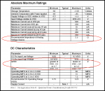
However, I must say that I'm rather puzzled by the data sheet. Does the "Impedance of Analog Voltage Source" apply to the Analogue Input(s) or to the Reference Voltage (AVDD)? 2.5 ohms seems incredibly low for an "input" (given that for the PICaxe it's 10 kohms). And I don't think I've ever seen an "Absolute Maximum" value to be "Recommended". :confused:

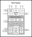
Also, it doesn't appear to be possible to connect the AVDD to an independently stabilised rail, it only seems to be permitted to deviate by a maximum of 300mV (or less) from the (digital) VDD. Details from the data sheet attached. As said above, I can't see any sign of a FVR in the block diagram.

uMFPU-V3ratings.pnguMFPU-V3_BlockDiagram.png

Cheers, Alan.
 

oracacle

Senior Member
you cant see a fvr, most likely because it doesnt have one, or at least doent allow access to it.

i would not even think about running the AVDD on a different voltage, run the entire circuit at a stabilsed voltage that wont reflect the droop of the battery, say 7v regulatd down to 5v. either that you will have to use the second ADC to create a refrence to correct the first adc.
 

ac246

New Member
Hi, Thanks for all your suggestions, i think i have worked it out now. I am reading in the voltage from an oxygen sensor from seeedstudio which is connected to an opamp. the output voltage seems to stay the same across the voltage range i am using. which is 4x1.2V rechargeable AA. By using the calibADC12 command on the picaxe i am able to work out the voltage from the opamp, and then convert this back into a percentage of oxygen.

The project is a datalogger to go into an abandoned mine to monitor air pressure, temperature, humidity and oxygen level. i want the whole unit to ideally to have self contained batteries such as AA within the casing although these are very limited in capacity. I want to be able to leave the datalogger in the mine for weeks at a time.

Next step is to try and get the whole circuit from 200mA to as little as possible between readings.

ultimately i am going to have to use a different power supply. even if i have to lug a car battery into the mine which can be several miles walk within the mine to get to the location.

Thanks.

Aaron
 

AllyCat

Senior Member
Hi Aaron,

Do you mean CALIBADC10, I wasn't aware there is a 12 bit version?

The PICaxe should be consuming less than 1% of that current and can be reduced to (much) less than 100uA by using its power saving measures (sleep, nap, disablebod, etc.). The FPU chip is probably the most power-hungry part, so you will need to determine how best to disable that (and the other sensors? ) when not required to make a calculation/measurement. "Weather Stations" can be designed to run for more than a year on a couple of AA cells.

Cheers, Alan.
 

oracacle

Senior Member
it should not be that power hungry, speciely in sleep mode

see aplication note 43
http://www.micromegacorp.com/appnotes.html#v3

that documant seem to show at 5v and 30mhz, you should still be drawing no more than around 80mA, and idle should be and idle at 43.7mA.

also i think ut will dpend on the picaxe in use, for an understanding of the less than 2mA draw that isbeing suggested by allycat
 

AllyCat

Senior Member
Hi,

AFAIK, the processing "core" of any PICaxe uses about half a milliamp when running at 4 MHz. Of course any additional components (LEDs, sensors, regulator, etc.) will add to the current drain from the supply rail (either externally or via the PICaxe's pins).

The project is a datalogger to go into an abandoned mine to monitor air pressure, temperature, humidity and oxygen level.
What types of calculation and measurements are you doing that needs a FPU and a 40-pin PICaxe?

If the PICaxe is going to spend most of its time sleeping, then it could be doing some fairly "serious" calculations instead. Or if it's just a "logging" application, then why not just store the "raw" data and then "Post Process" the numbers with a "proper" computer/application when the data is downloaded?

Cheers, Alan.
 

oracacle

Senior Member
for that matter is there any reason is there any reason why the system cant do the post proccessing.

also allycat, he is using the 12bit adc on the fpu for the 02 sensor, and the 10bit picaxe adc for voltage correction, unless i missunderstood something. after the data has been captured i dont know what sort of maths needs to be done, but i am reasonably sure that there are something that will be push the picaxe fairly hard, and will take along time to complete along with alot of programme space

I have been fettling on some future projects, laying down some ground work for them, one calculation requires T=f^2/2^x where x can be both positive, negative and will almost always be a decimal number. doing these sum the long way and writing the code for them is into degree level applied mathmatics and well beyound most people, even those who spent a life time designing things like quidence systems and satalites. things like the the FPU that can do that do that maths in less than 10ms will almost always be welcomed in those situations
 

AllyCat

Senior Member
Hi,

Yes indeed, you may be correct, but it really needs the OP to give some more details of the computations required and the logging interval, etc.. It's just that the when a "Project Plan" reaches a consideration to "lug a car battery into the mine which can be several miles walk within the mine to get to the location", then it may be time to "stand back" and see if any better alternatives exist.

He is indeed using a 12-bit ADC, but the "Reference" it's using is being measured by a 10-bit ADC, which in practice gives less than 10-bit resolution when using CALIBADC10 (particularly with a ~5 volt rail). If 12-bit accuracy / resolution is required, then perhaps a dedicated 12-bit I2C ADC chip should be used (probably with a less demanding input impedance specification)?

Certainly a FPU can do calculations impossible with PICaxe Basic, but speed is probably irrelevant (for a 24/7 logging application) and non-linear sensors often can be accommodated with a pre-calculated lookup table or two. And a spreadsheet program (e.g. Excel) on a PC (for Pre- or Post- Processing) may be far easier to program than an embedded FPU.

Cheers, Alan.
 

oracacle

Senior Member
yes i agree, also the fact that using a 12v battery would mean that ut would be regulated down and thus by the time it got to a point that the voltage droop got to the point of affecting the sensors the reg would most likely drop out alltogether.

it maybe worth while the op doing some experiments with other batteries, a 200mA draw on 2Ah battery used in remote control cars maybe worth looking into. I have a 2.5Ah 7.2 volts variant in the rail and i am really suprised at how long it lasts by comparison to the amount of draw, its in the region of several hours on constant use with a nema 17 mocro stepped, picaxe 28x2 and the good old fpu.

all in all we can only speculate unless more information is provided
 

Goeytex

Senior Member
The Picaxe current when active is approximately 500 microamps per MHZ of clock speed.
So at 4 MHz that is about 2 milliamps. Then add in any current from external pullups.
A 10K pullup with a 5V supply is 50 microamps. To reduce current further, higher value pullups
or the internal pullups can be used.

The FPU can be powered down completely while the Picaxe is asleep, using an external
switch (transistor). Then when the Picaxe wakes up to take a reading, it signals the
switch to power up the FPU.

Alternatively, the FPU can be eliminated, and the Picaxe only records the raw data. The math can be done
by software (excel?) later. This is probably how I would do it.
 
Last edited:
Top