First Project - Xbox 360 Controller Rapid Fire Mod

chigley

Senior Member
Hey all,

Just joined here yesterday. I've used PICAXE microcontrollers at college but I've never actually done a whole project with one from scratch. This seems to be the right place to come and ask for help if I ever get stuck!

I've been doing my research, and basically what I'm trying to achieve is the rapid fire controller mod for the Xbox 360. I'm relatively comfortable with electronics and soldering, and I've already had my controllers in pieces many times before. Hopefully I won't need to post here many times for help, I'm more of a "Google about and work it out myself" person rather than "find the appropriate forum and get the members to do it all for me" type.

One initial question I do have is the best way for the programme to work.

I figured I could either use HIGH and LOW on an output pin, and repeat this while the trigger is held down. When I simulate this in the Programming Editor, however, this is very slow. Is it slowed down in the editor so that I can see what's going on? Or would it actually be this slow if I were to try it out?

I also found the PWMOUT command, which also seems appropriate. Which of the two would you recommend, or is there an easier way that I have overlooked? It just needs to power/unpower/power/unpower an output pin consecutively whilst the trigger is held down.

My USB cable is on order, and I have access to anything else I at college. Before you say, yes I know I could just buy a preprogrammed PICAXE with instructions off eBay, but I'm doing this for personal achievement rather than to actually use it.

Look forward to hearing any responses!

Charlie
 

Andrew Cowan

Senior Member
High and low must be slowed down in the simulator, as in real life the gap is about 0.25ms.

This means:
High 0
low 0
high 0
low 0

Gives two 0.25ms pulses about 0.25ms apart.

However, I think this is too fast for the xbox to understand. I would imagine that for rapid fire, you would want pulses of 5ms or about that.

A
 

chigley

Senior Member
High and low must be slowed down in the simulator, as in real life the gap is about 0.25ms.

This means:
High 0
low 0
high 0
low 0

Gives two 0.25ms pulses about 0.25ms apart.

However, I think this is too fast for the xbox to understand. I would imagine that for rapid fire, you would want pulses of 5ms or about that.

A
So could I just use:

Code:
high 0
pause 5
low 0
high 0
pause 5
low 0
high 0
pause 5
low 0
And just play with the pause value until the Xbox detects it? Do you think the PWMOUT would be cleaner, or is that too complex?

Thank you :) Much appreciated
 

eclectic

Moderator
@chigley

in your code

Code:
high 0
pause 5
low 0
high 0
pause 5
You'll need a pause between low and high, otherwise,
your Xbox might just “see” a permanent high.

Have a look in Manual 2 for the commands
Toggle
Do /Loop /Until

And, rather than repeating “pause 5”, have a look for

“Symbol”

e
 

Andrew Cowan

Senior Member
eclectic - that's a great idea.

Code:
symbol timeperiod = 5

main:
if pin3 = 1 then fire
goto main

fire:
pause timeperiod
toggle 2
goto main
That should work - you just need to play with the time period.

PWMout is too fast for this (I think). A timeperiod value of 5 gives 200 shots per second.

A
 

chigley

Senior Member
OK thanks for the advice guys :) I'll have a play over the next couple of days and will see how I get on.

Cheers
 

alband

Senior Member
Might have got confused, but isn't this a "button" command question?

chigley: the button command act like your keyboard. If you press once, it will just enter the letter once, if you hold the button for a bit, it multipresses until you let go. The trimming can all be adjusted, (with considerable difficulty). I've never properly understood how to adjust the timing, but BB did a page on it: http://www.picaxeforum.co.uk/showthread.php?t=10864&
 

chigley

Senior Member
Hi again,

Sorry for the bump but I didn't really feel the need to make a new thread, just thought I'd update you with my progress so far for those who are interested.

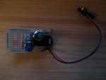
I've pretty much got my circuit working on the 08M prototype board now. I used an LED in place of the trigger output for the time being, and have two push to make switches playing the roles of the trigger switch and the mode changing switch. A photograph of my board is attached to this post.

There's just one more step left before I'm ready to start wiring it into my controller - a mode indicator LED. This will be a tri-colour common cathode LED which will be red/green/yellow depending on the mode.

I'm really impressed with the detail provided by the manual - I didn't have to ask here for help once! The only point where I had to read up on was for storing the rapid fire mode in the memory so that it is kept stored when power is removed, but I soon figured it out with the read/write functions.

Thanks to those who initially pointed me in the right direction, and hopefully I'll soon be posting a photo of the finished product!

Charlie
 

Attachments

eclectic

Moderator
@chigley

Feedback is always welcomed.

And, regarding your paragraph on reading the manual,

BB and Dippy will both want to frame your reply. :)

e
 

chigley

Senior Member
Literally, put it in a frame and keep it.

Our esteemed (grovel) moderators often, and correctly,
keep saying

Read the Manual please.

You have already! You may be a rarity. :)

e
Whoop go me :) After seeing so many idiots on other forums where I'm a regular, I always try my best to keep on everyone's good side when starting somewhere new!

I even read the rules when joining, which is a first for me! :eek:
 

BeanieBots

Moderator
Absolutely, so refreshing to have a poster let us know how things went.
One that has read.... well, now that is rare.
Looking for a frame right now.
Well done chigley.
 

chigley

Senior Member
Awwwwwh shucks :p

I'm guessing the tri-colour LED will be easy, just middle leg to ground and I have two output pins left spare. Should be arriving in a couple of days!
 

beaniecrocker

New Member
Um, what's so funny? :confused:


Thanks for these, but I've actually already got a switch installed in my controller. As for wiring them to the player 1 LED (which is powered with PWM), this is:

  • too fast
  • too messy as it only works when you're player 1

Thanks :)
depending upon which controller you have there are different constant power sources if you tell me if you have 2 large chips on the side of the board where the triggers mount or 1 on a 45 degree angle?
 

chigley

Senior Member
depending upon which controller you have there are different constant power sources if you tell me if you have 2 large chips on the side of the board where the triggers mount or 1 on a 45 degree angle?
Hey - thanks for joining just to help me out!! :)

It's the older matrix controller (with the two large chips), but I'd rather use a PICAXE so that I can have multiple modes and stuff.

Out of interest, where are the constant PWM sources if you don't mind?
 

beaniecrocker

New Member
a pause of 18-23 or so works for call of duty 4 but it varies depending upon games if you can put a potentiometer on it it works better
 

beaniecrocker

New Member
Hey - thanks for joining just to help me out!! :)

It's the older matrix controller (with the two large chips), but I'd rather use a PICAXE so that I can have multiple modes and stuff.

Out of interest, where are the constant PWM sources if you don't mind?
well over on the left hand side of the older style (trigger mount side) you will see 3 open solder points 1 square 2 round the square with the label r33 is a constant
 

beaniecrocker

New Member
Awwwwwh shucks :p

I'm guessing the tri-colour LED will be easy, just middle leg to ground and I have two output pins left spare. Should be arriving in a couple of days!
and im guessing that will work but if you just program your other output to say blink once twice or at the same speed of your rf all you have to do is wire it to the player 4 led left side and it will work just fine
 

chigley

Senior Member
and im guessing that will work but if you just program your other output to say blink once twice or at the same speed of your rf all you have to do is wire it to the player 4 led left side and it will work just fine
Yeah I don't want to use player 4 for two reasons:

  • I might be using it in split-screen games
  • without using flashes, you can't see what mode you're in (green/red/yellow is much better)

Cheers
 

beaniecrocker

New Member
but u have to power the chip on right are you gonna use an outside power source???? I am doing the same little project actually and I already have a rf controller that i actually bought the kit for with a preprogrammed picaxe08m chip and I wanted to see if I could do it myself
 

chigley

Senior Member
but u have to power the chip on right are you gonna use an outside power source???? I am doing the same little project actually and I already have a rf controller that i actually bought the kit for with a preprogrammed picaxe08m chip and I wanted to see if I could do it myself
Why do I need an outside power source? It can just go straight to the 3v inside the controller (or 5v if plug-and-play is in use, watch out for this when calculating resistance!)

My recommendation would be not to buy a preprogrammed chip, they're dirt cheap and it's much better if you make it yourself. I got my code working in under two hours. What I'm doing is I'm leaving the programming socket in my controller, so I can continue to reprogramme it for new games/patches or whatever without needing to take it all to bits every time.
 

beaniecrocker

New Member
I am about to buy the resistors Ic socket and stereo jack to do the same thing but I am a horrible programmer lets face It horrible with electronics but... I have soldered in tons of these pre programmed chips... and I wanted to figure it out myself It's just a bit overwhelming but I am definetly persistent. I found this program but I can't get the outputs to run I think It is my switch in the setup from the preprogrammed chip, the switch just connects to a ground and there is no lead to pin3 from a power source. but It works fine. when I put in this program...I can't get it to pickup the input I have pin 4 to the middle of the right trigger pot pin one to the player 4 led and the pin3 to a tact switch, tact switch to ground I am baffled

Setfreq m8

rapidoff:
Low 1
do
if pin3 = 1 then pause1
loop while pin3 = 0
goto rapidoff
pause1:
pause 1000
goto rapidon

rapidon:
Low 1
Pause 90
High 1
Readadc 4,b0
If b0 > 19 then Rapidfire1
If pin3 = 1 then pause2
goto rapidon

Rapidfire1:
Do
high 1
Low 4
Pause 36
High 4
Pause 106
b0=b0 and %00000000
Let dirs=b0
Readadc 4, b0
Loop while b0 > 26
goto rapidon

pause2:
pause 800
goto rapidon2

rapidon2:
Low 1
Pause 100
High 1
Readadc 4,b0
If b0 > 19 then Rapidfire2
If pin3 = 1 then pause3
goto rapidon2

Rapidfire2:
Do
High 1
Low 4
Pause 106
high 4
Pause 90
Low 4
Pause 101
Low 1
high 4
Pause 90
b0=b0 and %00000000
Let dirs=b0
Readadc 4, b0
Loop while b0 > 45
goto rapidon2

pause3:
pause 600
goto rapidon3

rapidon3:
Low 1
Pause 141
High 1
Readadc 4,b0
If b0 > 19 then Rapidfire3
If pin3 = 1 then pause4
goto rapidon3


Rapidfire3:
Do
High 1
Low 4
Pause 104
high 4
Pause 90
Low 4
Pause 100
Low 1
high 4
Pause 90

b0=b0 and %00000000
Let dirs=b0
Readadc 4, b0
Loop while b0 > 35
goto rapidon3


pause4:
pause 700
goto rapidon4


rapidon4:
do
high 0
high 1
readadc 4,b0
readadc 2,b1
if b0 > 22 and b1 > 22 then gosub halodual
if b0 > 22 then gosub halo
if b1 > 22 then gosub haloleft
if pin3 = 1 then exit
loop while pin3 = 0
pause 900
goto rapidoff

halo:
high 4
pause 106
low 4
pause 90
let dirs=%00000000
return

haloleft:
high 2
pause 106
low 2
pause 90
let dirs=%00000000
return

halodual:
high 4
high 2
pause 106
low 4
low 2
pause 90
let dirs=%00000000
return
 

chigley

Senior Member
Readadc 4,b0
Would be better if you made your own thread...

Looks like you ripped this code from a trigger-shooting rapid fire rather than switch-shooting type like you're trying to develop. That above line in your code is looking at the trigger pot as the input, so you'll need to change it to look at the switch (you can just use if pinx = 1 as long as there's a step down resistor)

For those interested in my project my tri-colour LED works fine, have it all in place :) All that's left to do is solder it all in now! I'm working on a PCB design first though.
 

inglewoodpete

Senior Member
beaniecrocker, please have a look at the sticky on how to use the forum. Then edit your last post and add CODE tags around your code. Long programs can get out of control on the forum.

Thanks
 

chigley

Senior Member
Hi again all,

Just wondering, is there any way to vary the output voltage when using high (or a similar function)?

My problem is with my tri-colour indicator LED (common cathode, with the anodes on an output leg each). For the three modes the LED should be green, red and then a mixed colour (described as yellow by the manufacturer).

When I've come to hook up the tri-colour LED, the red and green colours combined together look too similar to the red colour alone (the red is vastly overpowering the green, leading to a "faded red" rather than yellow). Is there a way to output fully green and less red, without using an additional resistor?

A resistor is not really an option as this would dim the red colour at all times, when it should only be for when the two colours are combined to make a third. An RGB LED isn't an option either as I don't have enough pins left and don't want to upgrade to the next chip up.

Much appreciated, hope that all makes sense!

Charlie
 

alband

Senior Member
Take a look at the PWM command on page 126 of manual 2. It is what you want but may be hard to fit into your code. :)
 

Andrew Cowan

Senior Member
PWMout on page 128 (manual 2) is more useful, as it continues in the background. The LED would seem to be on constantly (though at a lower intensity) if strobed at several kilohertz.

Note that it only works on certain pins.

A
 

chigley

Senior Member
What a coincidence, according to the manual the PWMOUT pin on an 08M is 2, which happens to be the pin on which my red anode is! Good stuff :)

I best have a play then! What am I trying to achieve, leaving the green on fully whilst only blinking the red so that it is less visible?
 

Andrew Cowan

Senior Member
leaving the green on fully whilst only blinking the red so that it is less visible?
That's right. Give an inital PWMout command, and then change the duty cycle to change the brightness.

Note - use the wizard in programming editor to get the values!

A
 

chigley

Senior Member
So far I've programmed the chip with a pwmout code but my LED isn't even lighting up? Am I missing something?

Used the wizard to get the values...
 

chigley

Senior Member
Well lest see what exactly is going on. Can you post you code...
Code:
pwmout 2,150,150
^ That's the most recent one I've tried, straight from the manual. I'd imagine that's too quick, but I tried increasing the values, tried using some from the wizard, and still no sign of life on the LED.

I know the circuitry is fine because high 2 works fine.

Cheers,

Charlie
 

alband

Senior Member
...:confused:should work
Is that the only command in your code or is it amongst other code.
If the latter, try it by itself straight out of that example in the manual where you got that bit from.
Have you tried using a simple high low routine with an adjusted pause in between, just to see if the LED can handle it.

Also, can you provide, the/a link to, datasheet for the LED.
 
Top