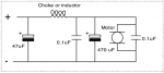
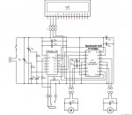
Getting better - you probably have 2 too many 100uF Electrolytice - on a small circuit one would be enough (or a single larger one) and it would normally be shown on the left of your circuit from +v to -v.
Oh that's right, you mentioned it above and I forgot to change it. Thanks for the catch
")
The purpose of the caps is for decoupling, but let me just make sure I'm 100% sure what that means. It essentially helps flatten out any voltage spikes/drops to keep voltage constant correct?
The smaller 100nF do get spread around the circuit physically as they do a very different job where distance matters to their effectiveness.
Building on that, the values of the caps are somewhat arbitrary. By that I mean there's values that can be too big or too small, but it's not as if there's a calculated range that it needs to be in right? What happens if the values are too big or too small? Why the two different types, is it because a larger capacitance need across V+/- and ceramic just don't get that big?
As a side test, I wired up a pot and used it to cycle through colors on an RGB LED. When initially hooking it up, I put a 100nF cap across the center pin to ground and it worked pretty good. I then took out the cap and noticed a HUGE difference. Without touching the pot, the LED would constantly flicker just a little bit. I realize it's just simple concept, but pretty cool to see in action none-the-less.
Sorry for the 20Q's and I truly appreciate all the help and feedback from everyone! For everything they've taught us in school, we've never covered what the different types of capacitors are used for.
RadioShack has a decent description page, but it's still kind of vague. I'd welcome any links on good descriptions!