Feeling the pressure!

John O

Senior Member
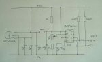
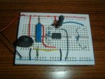
While I decide what's wrong with my HP03 pressure circuit, I decided to try an MPX4115A instead.

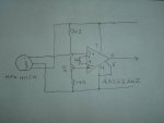
It seems to be working but, as the volatge swing is so small at the pressures we're interested in, I added an amplifier using a AD623 but I'm not having much luck with this either!

I'd hoped the attached circuit would give me a decent voltage swing between 0 and 4.9(ish) volts for an input differential of between 3.8 and 4.3 volts.

I've adjusted the 10-turrn pot to put 3.8 volts on pin 2 and the voltage from the MPX4115A is 4.09 volts. With the AD263 pin 5 grounded, it doesn't matter what gain resistor I use, I just get 0.09v at the output. With pin 5 open I just get virtually the supply volatge (5v) out.

Am I leading myself up the garden path here and the circuit will never do what I think it should or does the AD263 seem duff?

Thanks,

John.
 

Attachments

premelec

Senior Member
Without commenting specifically on the IN amp you've got I note that you are simply trying to amplify .5 volts to 5 volts - a paltry gain of x 10. All you need is an op amp with good common mode rejection and a stable reference to offset the base voltage of the transducer. This is called an expanded scale setup. Hope this helps you to a simple solution... :)
 

John O

Senior Member
I picked that amp because the output is supposed to swing fully between the supply rails and it's supposed to be easy to select the gain with a single resistor. My final design has two 10-turn pots. One to adjust the differential voltage and one to adjust the gain. That op-amp is mentioned in post #3 here but I think I'll go back to post #1 and start again!

I haven't spotted what's wrong but I'm starting to spend a bit too much time on the entire project that I'm starting to get frustrated easily and make mistakes (Picaxe is addictive and can damage your health!!). I'm awaiting delivery of another HP03 - one with a full-sized 0.1" header so I won't need an electron microscope to solder to it and is a better solution IF I can get it to work! But it's an opportunity to take a break while it's shipping :)


John.
 

John West

Senior Member
I tried to find a data sheet for the amp chip you're using. Couldn't find one online. I can't help without info on the chip. Sorry.
 

John West

Senior Member
Not my IP. Just my old eyes and a dim monitor. It looks like I need to figure out how to change the linked-word color in Firefox in order to see the linked words more clearly. I missed completely that that was a link.

I wonder why a web search of the part number didn't turn up the data sheet? Odd.
___
EDIT: I see John O had transposed the the first two digits of the part number in both his post #1 and on the schematic he provided. Question answered. I was looking for a nonexistent part. Those are hard to find.
 
Last edited:

John West

Senior Member
John O: Try using a couple of 10K resistors to make a 2.5 Volt divider, then hook pin 5 to that point instead of ground.

It looks like the gain resistor should be around 10K to 20K Ohm.
 
Last edited:

matherp

Senior Member
John O

I've got both a MPX4115A and AD623 in my parts box as I've used both previously. I've given up on the AD623 as I've never been able to get it to behave consistently sensibly but anyway I thought I'd mock up your circuit to test.

Initial results were basically as per yours i.e. no response.

Then I tried using a 2.5V reference - still nothing - the output sits at 2.5V

So I disconnected the MPX4115A and potential divider and replaced them with a type K thermocouple and set the gain to 1000 (100ohm resistor) - works perfectly - nothing wrong with the op-amp

Next I put a 100K resistor between the MPX and the op amp and left the gain at 1000 - now I'm getting some response to changing the trimmer pot but not a gain of 1000

Then I put a 470nF capacitor across the op amps positive input and ground and removed the gain resistor to give gain of 1 - it tracked perfectly.

Finally I put a gain resistor of 22K in to give a gain of about 5 and this also seems to work

So it looks like the MPX4115A is giving a very noisy signal which is somehow locking up the op amp or causing it to oscillate.

My final circuit which worked was a 470pf capacitor between the MPX output and ground as per the MPX manual, then a 100K resistor to the op-amp positive input and this connected to ground via a 470nF capacitor. This works with either a 2.5V or 0V reference.

Also make sure both the MPX and AD623 are both decoupled very close to their power pins

Hope this helps

Best regards

Peter

PS In the circuits I've built using the MPX4115 I use a MCP4324 18 bit I2C ADC. This gives accurate results with plenty of resolution without the need for any external amplification. I do still use an RC filter on the input to the ADC.
 
Last edited:

John O

Senior Member
Sorry about getting the chip's part number mixed up - that's due to the frustration I was feeling last night!

I have trouble spotting hyperlinks in another forum I'm in so I know they're easily missed. I'll try to remember to underline the non-obvious links I post.

Thanks for the suggestions and, matherp, many thanks for taking the time to breadboard it and resolve the problem.

I found a few problems last night - not least was the legs on the chip were only just about making contact with the breadboard I'm using.

Unfortunately, I should have stopped earlier last night because I ended up letting the magic smoke out of the MPX4115A :( It was pretty much one of those "I knew that was going to happen" moments.

I'm very interested in your MCP3424 solution though. I'd better buy half a dozen MPX4115A's before I start playing! :)

Thanks,

John.
 

John West

Senior Member
I don't know how much you're paying for the AD623, but I'd expect an instrumentation amp like that one to cost more than a generic op-amp as they are a special purpose device.

As you're having difficulty with them, and apparently will need to add extra components to make them work, why not just buy a cheap op-amp that will work splendidly in your ap without all the extra parts and problems?
 

matherp

Senior Member
I'm sure John W's approach will work but my motto is never use an analogue part when you can do it digitally :)

Attached is tested code to read in the output from a MPX4115A using a MCP432x ADC and convert it to millibars. The ADC reads +/- 2.048V in 16 bit differential mode so a voltage divider is used to set the negative input of the ADC at 2.5V and then the +ve will be roughly 4.0V coming from the MPX4115A for normal atmospheric pressures

Code:
#picaxe 20X2
setfreq m8
' Measuring atmosperic pressure with a MPX4115A
' Analogue to digital conversion using a MCP3421
' MPX output to V+, 2.5V to V-
' ADC in 16 bit mode
symbol mb900=17429 'ADC reading for 900Mbar, then add 72.288 counts per mbar
symbol adj0=72
symbol adj1=b4 'used to add 1 count every 4 mbar
symbol adj2=b5 'used to add 1 count every 24 mbar
symbol mbar=w3
'
hi2csetup i2cmaster, %11010000, i2cfast, i2cbyte
hi2cout (%00011000) ' set for 16 bit continuous conversion
do
	hi2cin (b1,b0,b2) ' read in the ADC reading and the status byte
	adj1=0
	adj2=0
	w1=mb900
	mbar=900
	do while w0>w1
		inc mbar
		w1=w1+adj0
		inc adj1
		if adj1=4 then
	 		inc adj2
	 		w1=w1+1
	 		adj1=0
		endif
		if adj2=6 then
			w1=w1+1
			adj2=0
		endif
	loop
pause 1000
sertxd ("Pressure is ",#mbar," millibars",13,10)
loop
 

John O

Senior Member
Thanks both. I must admit that I tend to have more luck with digital circuits so I think I'll go with these. I was going to ask if you'd connected it with differential inputs but you've answered that one.

I'll practice with SMDs one day but a small company in Scotland makes breakout boards and, as they will source the chips, I can circumvent RS's minimum order charge.

I'll also have another go with the HP03 (when the "full-sized" version arrives) but, as its maths virtually needs a Picaxe to itself, the MPX4115A has to be a better approach once the narrower resolution is overcome.

Thanks again,

John.
 

TAMeyer

Member
Old Part?

John:

I don't have an answer, but a couple of questions may be worth considering.
The part number you listed caught my attention as I use a Freescale sensor for a CPAP monitor.

FYI..the datasheet for your sensor was archived by Freescale in 2005.
It also measures a *wide* range of pressure

Model 4115
15 to 115 kPa (2.2 to 16.7 psi)
0.2 to 4.8 Volts Output

Compare this to:
0 to 3.92 kPa
1.0 to 4.9 V Output
…for a model 5004G.

http://www.freescale.com/files/sensors/doc/data_sheet/MPXV5004G.pdf

So you will need a much greater pressure swing for a voltage change to occur. Which, would, as I thought through all this, create a need for an op-amp.

You didn’t mention what you are monitoring in your HP03 post, but it appears the 03 part is for a barometer. MatherP’s millibar code seems to confirm this. Is that the application?

An open question: How does one test a barometer monitor?
Aside from creating a small airtight chamber, you would have to make adjustments over days and weeks correlating with published WX reports…no?

Background

Like you I felt an op-amp would be needed. Using Dr. Acula’s tutorial and a TLC2274, I was successful in getting decent readings, good enough for ADC.
http://focus.ti.com/docs/prod/folders/print/tlc2274.html

The op-amp is in the upper left hand corner of the attached schematic. It was drawn almost verbatim to what the Dr. presented.

In testing the setup I also found two points in note:
1/ Placing a LED on the op-amp output, I could see a lot of “chatter” in the data stream. That is to say the LED was blinking at an unusually high rate. An averaging subroutine was used to smooth the readings.
2/ I didn’t really need a op-amp. The output from my sensor was enough to work with ADC directly as the pressure range was so small.


Terry
 

Attachments

Last edited:

John O

Senior Member
Yes, as you've guessed, it's for a barometer/weather station. You're right that the MPX4115A operates over a wide range (15 - 115 kPa). The HP03 is a bit better at 30 - 110 kPa. Considering that, ideally, I'd expect a range of 90 - 110 kPa to be more suitable, it's amazing that nobody seems to make a sensor in that range. A manufacturer wouldn't be able to make 5 volt supply, 90 - 115 kPa, 0 to 5v (or 0 to 1023) output sensors fast enough!

Whatever the sensor, it would seem that only the zero and span points are easily adjustable without resorting to tweaking the code to straighten out any kinks in the middle. I know my height above sea level and can refer to the local airport's QNH/QFE readings so I suspect that's how I'll be calibrating it over a period of time.

John.
 

eclectic

Moderator
Yes, as you've guessed, it's for a barometer/weather station. You're right that the MPX4115A operates over a wide range (15 - 115 kPa). The HP03 is a bit better at 30 - 110 kPa. Considering that, ideally, I'd expect a range of 90 - 110 kPa to be more suitable, it's amazing that nobody seems to make a sensor in that range. A manufacturer wouldn't be able to make 5 volt supply, 90 - 115 kPa, 0 to 5v (or 0 to 1023) output sensors fast enough!

snippedJohn.
Not perfect, and just for a laugh.

http://uk.farnell.com/sensortechnics/144sc0811-baro/pressure-sensor-barometric/dp/540894
Datasheet
http://www.sensortechnics.com/download/144s-pcb-005.pdf

Ec
 

John O

Senior Member

Attachments

MartinM57

Moderator
Why the MCP3422 complexity? Surely a READADC10 in the PICAXE would be good enough for a weather station (1 part in 1024)?

The datasheet for MCP3422 says " Ideally, the input source impedance should be zero. This can be achievable by using an operational amplifier with a closed-loop output impedance of tens of ohms"...your 100k resistor is about as far away from zero ohms as it can be. I'd ditch it completely (why did you put it in?) and the 470pf after it - especially the latter as the S/H input capacitor in the DAC is only 3.2pF (I can't really believe that to be honest - but that's what the datasheet says).
 

matherp

Senior Member
John

for the input to the MCP I would replace the 100K resistor with something smaller as it seems to show a lower input impedance than an op amp. I use 10K and then a 1uF capacitor to ground from the input pin. Other than that it looks fine. On the spare inputs, personally I would tie them to pin 2 as that makes the physical wiring easy 2-7-8. Finally, there is no real point in the 1K resistors either side of a 10K pot - 10K resistors perhaps - I would also have a 0.1uF capacitor from the centre tap of the pot to ground.

best regards

Peter
 

John O

Senior Member
Thanks for the replies.

As I understand it, the range isn't really 1 in 1024 because the useful range of the MPX4115A is so small.

Peter, I've reduced the input resistor to 10k and cut and pasted your code from your post above. Changed the #picaxe deinition to an 18M2, and commented out the setfreq - I haven't yet checked out the implications of raising the frequency for other parts of the final code I'll be using so thought it best to check as standard.

The result is as per the attached iamge:

So, :) :) Many thanks. I'll definitely get the HP03 running one way or another because it would be interesting to let them run side by side.

But, again, many thanks...

John.
 

Attachments

John O

Senior Member
Why the MCP3422 complexity? Surely a READADC10 in the PICAXE would be good enough for a weather station (1 part in 1024)?
I must admit, I thought that as well when I started :) The problem is that I haven't found a single weather station circuit that doesn't have something to give the MPX4115A a bit of a leg up.

The HP03 is better in that it has a smaller range.

John.
 

matherp

Senior Member
John

Great news it is all working. I assume you are near sea level in the Wirral. My house is at 420ft above sea level so my readings are about 14mbar lower (30ft /mbar) than "offical" readings which are always quoted as at sea level. I just put this in as a fudge factor in my program to give sea level pressure.

best regards

Peter
 

eclectic

Moderator
To John and Peter.

Where's the best, as in fastest
place to get one of these HP03 sensors?

(This Forum costs me a small fortune. :)

e
 

MartinM57

Moderator
So thinking out loud...

Pressure for a weather station = min 95kPa, max 105kPa (?)

The MPX4115 gives out about 4v at 95kPa and 4.5v at 105Kpa - so 10kpa change = 500mV change

10 bit PICAXE resolution is 1023 steps over 5v i.e. 4.8mV per step

So 500mV change can be resolved into 500/4.8 steps ~= 104 steps. Let's say 100...

So you can measure 10kpa pressure change as 100 different READADC10 values - so a resolution of 0.1kPa.

Is that too coarse for what you are doing?
 

John O

Senior Member
Yes, I'm quite near the north coast of the Wirral so we're pretty-well at sea level. In fact, we rely on some sea defences.

I must admit, measuring pressure has been a lot more complicated than I expected but that's the last part of the jigsaw - finally!

Thanks again,

John.
 

John O

Senior Member
To John and Peter.

Where's the best, as in fastest
place to get one of these HP03 sensors?

(This Forum costs me a small fortune. :)

e
The only two places I've seen are Futurlec and Ocean Controls - both in Australia. Futurlec took 32 days AFETR I'd received their 'shipped' email. Ocean Controls took about 8 days. Mind you, neither of them sent what I ordered :)

John.
 

matherp

Senior Member
Martin

0.1kpa = 1mbar so by your calcs that is roughly 1 bit of resolution? As per a previous thread a 10 bit picaxe only seems to give 8 bits of true accuracy so that is 4mbar which is not good enough. The thing I like about the MCP432x range is that they seem so tolerant of the quality of the input signal and always give a good result. The other thing is that because they have a x2, x4, x8 programmable internal amplifier and differential inputs you can use them with no other signal conditioning for pretty much everything from strain gauges, through thermocouples, to (relatively) simple stuff like the MPX

The interesting question I haven't researched properly is whether there is a picaxe where you can set vref- to say 3.8V and vref+ to say 4.8V and get 10 bit resolution between them. That would certainly do the job for a barometer

best regards

Peter
 

John O

Senior Member
So thinking out loud...

Pressure for a weather station = min 95kPa, max 105kPa (?)

The MPX4115 gives out about 4v at 95kPa and 4.5v at 105Kpa - so 10kpa change = 500mV change

10 bit PICAXE resolution is 1023 steps over 5v i.e. 4.8mV per step

So 500mV change can be resolved into 500/4.8 steps ~= 104 steps. Let's say 100...

So you can measure 10kpa pressure change as 100 different READADC10 values - so a resolution of 0.1kPa.

Is that too coarse for what you are doing?
It certainly seems plenty!

I've run out of breadboards (!) but it should be simple enough to run it alongside the "complicated" one to see what happens. I'm all in favour of KISS if possible. :)

KISS, Digital, Analogue in that order, me!

John.
 

MartinM57

Moderator
Why not just jumper the output of the current sensor also to an ADC pin (if you currently have a spare one) on the current PICAXE on the current breadboard - then you can compare, inside the code, the READADC10 value with the n'ty bit MCP value you get from the I2C bus...
 

matherp

Senior Member
I use the AP but only because it was at the time the cheapest version - I think electrically they are the same
 

eclectic

Moderator
The only two places I've seen are Futurlec and Ocean Controls - both in Australia. Futurlec took 32 days AFETR I'd received their 'shipped' email. Ocean Controls took about 8 days. Mind you, neither of them sent what I ordered :)

John.
Hmm.

I think I'll play with the
MPX4115A and readadc first.

Thanks for the warnings..
e
 

MartinM57

Moderator
Sounds good.

Also remember the difference between absolute accuracy of the result i.e when you say 992mbar, that is subject to an accuracy tolerance (5% or whatever) from the sensor and an accuracy tolerance (2% or whatever) from the ADC...(so could be ~7% out from the actual value)

...and the resolution that you can measure (say 0.1mbar)

High resolution doesn't imply high accuracy at all....
 
Last edited:

John O

Senior Member
So thinking out loud...

Pressure for a weather station = min 95kPa, max 105kPa (?)

The MPX4115 gives out about 4v at 95kPa and 4.5v at 105Kpa - so 10kpa change = 500mV change

10 bit PICAXE resolution is 1023 steps over 5v i.e. 4.8mV per step

So 500mV change can be resolved into 500/4.8 steps ~= 104 steps. Let's say 100...

So you can measure 10kpa pressure change as 100 different READADC10 values - so a resolution of 0.1kPa.

Is that too coarse for what you are doing?
My lousy maths isn't helping me work this out but the 3.79 - 4.25 volt range seems to be most commonly reported for expected pressures = 460mV.

Instead of better than 100 steps for the 10 kpa change, it's about 95 so the resolution would be less than 1 mBar which might result in 2 mBar steps which isn't really fine enough.

But I could be way off the mark!

John.
 
Top