Fan controller circuit

greencardigan

Senior Member
Hi,

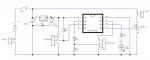
I'm planning to use an 08M to control some 12V fans.

The 08M will read temp from DS18B20 and PWM fans via a FET.

Can anyone provide any comments on my circuit schematic or code.

Code:
symbol OFFTEMP = 432 	'degrees x 16
symbol ONHALFTEMP = 448	'degrees x 16
symbol ONFULLTEMP = 464	'degrees x 16

symbol TEMP = w0

for b2 = 1 to 4	'flashes led
	high 1
	pause 20
	low 1
	pause 200
next

do
	high 1	'flashes led on temp read
	pause 20
	low 1

	readtemp 4, TEMP		'TEMP = degrees x 16

	if TEMP >= ONFULLTEMP then
		pwmout 2,0,0
		high 2
	else if TEMP >= ONHALFTEMP then
		pwmout 2,255,600
	else if TEMP <= OFFTEMP then
		pwmout 2,0,0
	endif

	pause 5000
loop
Thanks,
Brad
 

Attachments

BeanieBots

Moderator
All looks reasonable except you've used readtemp and commented temp*16.
I think you meant to use the readtemp12 command.
As for the circuit, it should work OK but I would be tempted to put a resistor between gate and PICAXE (just in case) and also fit a diode across the fan to catch any back emf that could over-volt the FET.

I'd also consider increasing the control range of the fan speed. Rather than just a simple set speed determined by temp, a good challenge would be to make the speed proportional to how much over-temp is detected. Probably not required in your application but you have the required hardware to make it possible so for me the temptation would be too great.

Not sure about your pwmout values. Double check them.
I'd use high/low commands for full on/off.
 

greencardigan

Senior Member
All looks reasonable except you've used readtemp and commented temp*16.
I think you meant to use the readtemp12 command.
As for the circuit, it should work OK but I would be tempted to put a resistor between gate and PICAXE (just in case) and also fit a diode across the fan to catch any back emf that could over-volt the FET.

I'd also consider increasing the control range of the fan speed. Rather than just a simple set speed determined by temp, a good challenge would be to make the speed proportional to how much over-temp is detected. Probably not required in your application but you have the required hardware to make it possible so for me the temptation would be too great.

Not sure about your pwmout values. Double check them.
I'd use high/low commands for full on/off.
Thanks for the comments however I built the circuit before I had a chance to read any responses here. It seems to work as expected.

I'm using brushless DC fans and I don't think they require a diode. Yes? No?

Yes, I had thought of making the fan speed proportional to the measured temp. Might try it sometime.

Code being used atm.

Code:
symbol OFFTEMP = 424 		'degrees x 16
symbol ONHALFTEMP = 448		'degrees x 16
symbol ONFULLTEMP = 464		'degrees x 16

symbol TEMP = w0

low 2

for b2 = 1 to 4			'flash LED on power on
	high 1
	pause 20
	low 1
	pause 200
next

do
	high 1			'flash LED on temp read
	pause 20
	low 1

	readtemp12 4, TEMP		'TEMP = degrees x 16

	if TEMP = 0 then
		for b2 = 1 to 4			'flash LED if no temp data
			high 1
			pause 200
			low 1
			pause 100
		next
		high 1
	else if TEMP >= ONFULLTEMP then
		pwmout 2,0,0
		high 2
	else if TEMP >= ONHALFTEMP then
		pwmout 2,50,75
	else if TEMP <= OFFTEMP then
		pwmout 2,0,0
		low 2
	endif

	debug w0
	pause 5000		'pause 5 seconds
loop
 

BeanieBots

Moderator
I notice you have put in a trap for "no temperature".
Presumably because there is possibility that the sensor might be disconnected?
If that is the case, then I would failsafe the code and assume maximum temperature under such conditions. That is, put the fan on full as well as indicate visually that there is a fault.

If you have a 'scope, then have a look at the turn off voltage across the FET. If it looks clean then leave off the diode. I'd fit one as a matter of course anyway. Even just the connection leads can be enough inductance to produce enough voltage to unduely stress the FET. For the sake of a few pence it could save you significant grief a few years later.
 

greencardigan

Senior Member
I notice you have put in a trap for "no temperature".
Presumably because there is possibility that the sensor might be disconnected?
If that is the case, then I would failsafe the code and assume maximum temperature under such conditions. That is, put the fan on full as well as indicate visually that there is a fault.
Yes, that was to catch any sensor problems. You're right, i will want the fans to come on.

If you have a 'scope, then have a look at the turn off voltage across the FET. If it looks clean then leave off the diode. I'd fit one as a matter of course anyway. Even just the connection leads can be enough inductance to produce enough voltage to unduely stress the FET. For the sake of a few pence it could save you significant grief a few years later.
No scope but i'll add a diode anyway.

Thanks.
 

greencardigan

Senior Member
Diode good idea. Also maybe a small cap across motor?

Put this in your Data Sheet folder...
read it first though.
The bit below "PWMing the Fan Directly" is interesting.

http://www.maxim-ic.com/appnotes.cfm/appnote_number/1784
Thanks. A nice easy to understand article. I learnt a thing or two.

Below is my latest and hopefully final version of code.

The fan speed is now directly proportional to the temp.
It also has seperate on and off temps to stop fans turning on and off if the temp fluctuate around the on temp.

Code:
SYMBOL MAXTEMP = 480	'temps are degrees x 16
SYMBOL MINONTEMP = 432
SYMBOL MINOFFTEMP = 424

SYMBOL MAXSPEED = 200	'must be <= 4 x pwm period (50)
SYMBOL MINSPEED = 50	'must be high enough to start fan

SYMBOL TEMP = w0
SYMBOL SPEED = w1

w2 = MAXTEMP - MINONTEMP	'temp range
w3 = MAXSPEED - MINSPEED	'speed range
w4 = w3 / w2			'interger part of ratio
w5 = w3 // w2			'remainder of ratio

for b12 = 1 to 4		'flash LED on power on
	high 1
	pause 20
	low 1
	pause 200
next

do
	high 1			'flash LED on temp read
	pause 20
	low 1

	readtemp12 4, TEMP	'read temp from DS18B20
	
	debug

	if TEMP = 0 then
		for b12 = 1 to 4			'flash LED if no temp data
			high 1
			pause 200
			low 1
			pause 100
		next
		high 1
		pwmout 2, 0, 0
		high 2				'fan on high if no temp data
	else if TEMP > MAXTEMP then
		pwmout 2, 0, 0
		high 2
	else if TEMP >= MINONTEMP then
		SPEED = TEMP - MINONTEMP * w4			'convert integer part of temp to speed
		SPEED = TEMP - MINONTEMP * w5 / w2 + SPEED	'convert remainder part and add interger part
		SPEED = SPEED + MINSPEED
		pwmout 2, 50, SPEED
	else if TEMP < MINOFFTEMP then	'fan will stay on low between MINONTEMP and MINOFFTEMP
		pwmout 2, 0, 0
		low 2
	end if
	
	pause 5000
loop
 

BCJKiwi

Senior Member
Well you have two issues for which I gave you the pointer previously.

When you do this bit of code;
w2 = MAXTEMP - MINONTEMP 'temp range
w3 = MAXSPEED - MINSPEED 'speed range
w4 = w3 / w2 'integer part of ratio
w5 = w3 // w2 'remainder of ratio

You will get very inaccurate results.
Test different values in you calculator and in the simulator and compare.
You will find big jumps in the simulator integer math results at certain values.
The link I referenced earlier has all the discussion and workarounds on dealing with these issues.
 

greencardigan

Senior Member
Well you have two issues for which I gave you the pointer previously.

When you do this bit of code;
w2 = MAXTEMP - MINONTEMP 'temp range
w3 = MAXSPEED - MINSPEED 'speed range
w4 = w3 / w2 'integer part of ratio
w5 = w3 // w2 'remainder of ratio

You will get very inaccurate results.
Test different values in you calculator and in the simulator and compare.
You will find big jumps in the simulator integer math results at certain values.
The link I referenced earlier has all the discussion and workarounds on dealing with these issues.

OK, I ran the following code in simulator for about 30 or so input combinations.

Code:
symbol num1 = 5025
symbol num2 = 1000

w0 = num1 / num2
w1 = num1 // num2
Every case came out the same as calcs done in excel. I have reviewed your previous link again and also this thread http://www.picaxeforum.co.uk/showthread.php?t=8564

I think for my application the calcs give 100% accurate results.

Unless you can show me some numbers that give inaccurate results, I am convinced that this code is perfectly OK.
 

BCJKiwi

Senior Member
if you divide 49 by 49 you will get 1
if you divide anything from 49 to 97 by 49 you will get 1

so you then use the modulus to get the bit left over and you have to deal with the number in two or more parts.
If the bit left over begins with zero then the zero gets dropped.
i.e. if the the value is 50 you get 1.2 instead of 1.02
If the value is 53 you get 1.8 instead of 1.08 ( this is equivalent to a starting number of 88 not 53!)

The basic principle is to multiply up the first number by a factor so it will always be under 65535 with the biggest number you are likely to get. Divide that, then manipulate the result to suit.
e.g. 53 *500 /49 = 540.8163 (integer 540)
540.8163 / 5 = 108.16 (Integer 108)
OR
53 *500 /49 /5 (integer 108)

Use the 108 value in the rest of your program allowing for the fact that it is actually 100 times too big - this doesn't matter to the program until it comes time to display or otherwise the real number is required. At this time you can manipulate it for display purposes by adding in the '.' at the relevant position. Your code and discussion does not indicate you want to display this data anywhere.

You have just improved you accuracy significantly.

Alternatively use some smarts to manage the modulus leading zero issue, or use 32 bit math - all explained in the link.

How big an issue this is depends on the number ranges you have to deal with, which you have not advised as you have only indicated the same sample values until this last post.

If the numbers are always orders of magnitude apart with the divisor always being the smaller than you may be OK, but as noted above, I don't know if this is the case as you did not respond the request for the ranges of numbers way back in post #4 of your other thread.
 
Last edited:

greencardigan

Senior Member
OK, taking your examples.

50 divided by 49 = 1.0204....
50 / 49 = 1
50 // 49 = 1
1 divided by 49 = 0.0204....

53 divided by 49 = 1.0816....
53 / 49 = 1
53 // 49 = 4
4 divided by 49 = 0.0816....

There you go. You got you dropped 0 back.
 

BCJKiwi

Senior Member
OK do it your way - sorry but I've had enough of this.
OK apologies, my response was not very helpful.
The numbers I chose for my example were not the best ones and do not illustrate the point I was trying to make very well.

Its just that I was trying to assist. Your original query was:- "I came up with the code below. Is this the best way to go about this??"

The issues I raise are real. I have indicated under which situations they may be a problem. Whether or not they will be a problem in your code I don't know because I don't know what numbers you will be using.
I have shown you how to avoid using the modulus altogether which is one of the problem areas.

You now seem happy with what you have so please continue.
 
Last edited:
Top