My PWM/MOSFET circuit for windmill load control was progressing nicely. It was driving fairly substantial test loads (about 6A at 120V fullwave rectified, but unfiltered, mains AC). The PWM signal to the MOSFET gate was clean as a bean (at 500Hz and a bit over 4V) and the MOSFET got barely warm (over at a range of duty factors). The previous PIcaxe startup issues I was having b/f were resolved and all was looking good until the MOSFET(s) starting failing (Drain shorted internally to Source). The fails occured (twice so far) immediately when the load power was applied as evidenced by the load (high wattage light bulbs) going immediately to full brightness. Both the Picaxe and driver were powered up at the time.
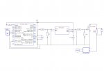
Heeding previous advice, I have attempted a schematic diagram (using DesignSpark PCB). On attempting to attach the file however, I find that the max allowable .bmp file is 19.6KB whereas my schematic is 3.5 MB! I suppose it could be trimmed down somewhat but at 19.6KB I doubt there would be much left (& .bmp seems to be the only file type DesignSpark will create that is acceptable for upload).
Anyhow, the MOSFET is a IRL640 (200V, 17A, logic level gate) and the driver is a MCP1407. The Picaxe/driver 5v supply is transformer isolated from the 120VAC supply.
Can anyone offer any suggestions as to why the MOSFET is failing? Maybe feeding the MOSFET unfiltered rectified AC is causing it grief (?).
Also, can anyone please tell me if a schematic pin can be attached to a shape (in DesignSpark PCB)??
Also, also, why does the forum have to go off line every day around 0300(?) GMT?
")