Fade through rainbow spectrum with rgb leds

westaust55

Moderator
Which PICAXE chip are you using?

Can you post you code. You may be quite close to a working solution and folks here can help you get that going. Possibly a better way to learn.

Have you tried a search of the PICAXE forum as using PWM and other means for chips with limited PWM channels as the basis has been discussed here many times.
Some of those past posters may not see you current request.

Here is a start for you: http://www.picaxeforum.co.uk/showthread.php?21497-RGB-fading-with-two-PWMs
 

nick12ab

Senior Member
I bought an rgb led strip 12v and I want it to fade through the colors of the rainbow.
What RGB strip? Common anode or common cathode? If it's common cathode then remember you cannot control the anodes with NPN transistors directly from a PICAXE I/O pin, or indeed PNP transistors due to the high voltage.

You can use an NPN/PNP combination (with the NPN driving the base of the PNP) to create an 'open collector' output on the PICAXE. Do not do this by setting the pin as an input instead of high because the clamping diodes will turn on the transistor instead. Don't forget resistors.

It's helpful to post the circuit diagram and code for things you've tried so that flaws can be pointed out.
 

Bill.b

Senior Member
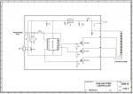
This is a sample code for controlling a RGB LED strip up to 5m long


The PICAXE is a 14m2 as this is the smallest to have 4 PWM outputs


Code:
'loop RGB LED Control
'May 2012
'Picaxe 14M2
#picaxe 14m2
#No_Data

symbol counter 		= W2
symbol Green	= W3
symbol Blue 	= W4
symbol loopcount	= b0

symbol Redout	= b.2
symbol Blueout	= c.0
symbol Greenout	= b.4

dirsb=%00011111
dirsc=%00000111
pwmout Redout,100,0
pwmout Blueout,100,255
pwmout Greenout,100,0
main:

gosub fade
'
goto main


fade:	

	for counter = 0 to 255
		  pwmduty Redout,counter
		  w5 = 255-counter
		  pwmduty Blueout,w5
		  pause 10
	 next counter
	 pause 400
	 for counter = 0 to 255  
		  pwmduty Greenout,counter
		  
		  w5 = 255-counter
		  pwmduty Redout,w5
		  pause 10
	 next counter
	 Pause 400
	 pwmduty Redout,0
	 pause 200
	 for counter = 0 to 255
		  pwmduty Blueout,counter
		   w5 = 255-counter
		  pwmduty Greenout,w5
		  pause 10
	 next counter
	 pause 400
	 
	for counter = 0 to 255
	 w5 = 255-counter
		  pwmduty Blueout,w5
		  pwmduty Redout,counter
		  pwmduty greenout,counter
		   
		  pause 10
	 next counter
	 pause 400
	for counter = 0 to 255
		 
		  w5 = 255-counter
		  pwmduty Blueout,counter
		  
		   
		  pause 10
	 next counter
	 pause 400

	return
RGBLEDControl.jpg

Bill
 

PaulRB

Senior Member
Hi plasmaninja,

I've been working on the HBS to RGB idea recently, similar to your Arduino example. Here's my code.

First the variable and pin symbols (I'm using a 20m2):

Code:
symbol	LED_Red = C.2
symbol	LED_Grn = C.3
symbol	LED_Blu = C.5

symbol	RedLevel = b13
symbol	GrnLevel = b14
symbol	BluLevel = b15
symbol	LEDHue = w8
symbol	LEDHueLo = b16
symbol	LEDHueHi = b17
symbol	LEDBright = b18
symbol	LEDSat = b19
Notice that LEDHueHi and LEDHueLo are the most and least significant bytes of LEDHue. The value of LEDHue must be kept between 0 and 767, LEDBright and LEDSat between 0 and 255 (obviously - they are byte variables!)

This code sets up the variables and PWM outputs initially:

Code:
	LEDHue = 0
	LEDBright = 0
	LEDSat = 255
	RedLevel = 0
	GrnLevel = 0
	BluLevel = 0
	pwmout LED_Red, 62, RedLevel
	pwmout LED_Grn , 62, GrnLevel
	pwmout LED_Blu, 62, BluLevel
The value of 62 was chosen so that a duty cycle of 255 corresponds to 100%.

Here's the code that converts HBS to RGB, and sets the PWM duty for the 3 outputs:
Code:
	RedLevel = LEDHueLo ^ 255
	GrnLevel = LEDHueLo
	BluLevel = 0
	
	if  LEDHueHi >= 1 then
		swap RedLevel, BluLevel
		if LEDHueHi = 2 then
			swap GrnLevel, RedLevel 
		else
			swap GrnLevel, BluLevel 
		end if
	end if

	w0 = RedLevel * LEDSat : RedLevel = LEDSat ^ 255 + b1
	w0 = GrnLevel * LEDSat : GrnLevel = LEDSat ^ 255 + b1
	w0 = BluLevel * LEDSat : BluLevel = LEDSat ^ 255 + b1

	w0 = RedLevel * LEDBright : RedLevel = b1
	w0 = GrnLevel * LEDBright : GrnLevel = b1
	w0 = BluLevel * LEDBright : BluLevel = b1
	
	pwmduty LED_Red, RedLevel
	pwmduty LED_Grn, GrnLevel
	pwmduty LED_Blu, BluLevel

	sertxd (" H=", #LEDHue, " B=", #LEDBright, " S=", #LEDSat, "-> R=", #RedLevel, " G=", #GrnLevel, " B=", #BluLevel, cr)
The sertxd is just for debugging purposes, not needed once tested. w0, b0 and b1 are used temporarily in the calculations, b0 and b1 are the least and most significant bytes of w0.

Hope this helps, feel free to ask any questions.

Paul
 
Last edited:

PaulRB

Senior Member
Here are a couple of pics of the project that code is from. I constructed 2 rgb led modules which run off a 9V stabilised supply. They are driven by the picaxe via 3 of the darlingtons in a uln2803.

20130511_184217.jpg20130511_133832.jpg
 

PaulRB

Senior Member
This may be why you're "not having much success" (you didn't really say what was wrong exactly).

With common cathode displays, you ideally need to be using "high-side" drivers. These are normally PNP rather than NPN like your tip102. The picaxe outputs may not be able to switch them on fully, or at all, if used as high side drivers.

Because I constructed my LED modules from individual red, green and blue LEDs, I was able to wire them as common anode.

Paul
 
Top