External I2C ADC led driver

sniper887

Member
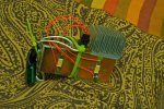
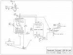
This is a constant-current LED driver I made using the Picaxe 18X, ADS1115 external I2C analog to digital converter, and an IGBT to do the switching. Wanted to make it so it fits into a light socket with a socket to outlet adaptor. I've determined the LEDs need more heat sink area than they currently have. After I built this I also learned (on here) about the benefit of using MOSFET drivers, especially at high PWM frequencies, and perhaps using an inductor on the output. I'm trying to figure out how to select the proper inductor value with the available PWM frequencies on Picaxe chips.

Code:
i2cslave %10010000,i2cfast, i2cbyte
pause 50
writei2c (%00000001,%01011110,%10000011)'config register
pause 50
writei2c (%00000010, $80,$00)
pause 5
writei2c (%00000011, $7F,$FF)
pause 5
writei2c (%00000000)
pause 50
w1 = 350
w2 = 450
start:

pwmout 3, 255, w1

gosub getcurrent

if w0 < w2 then

w1 = w1 + 1 max 1023

endif

if w0 > w2 then

w1 = w1 - 1 min 10

endif
'debug
goto start

getcurrent:
w0 = 0
w5 = 0
w6 = 0
writei2c (%00000000)
readi2c 0, (b1,b0)

return
 

Attachments

Last edited:

fernando_g

Senior Member
Nice project! How did you do the boards? Did you mill a blank board?

Now;
The classic inductor equation for a buck converter is:

L = [(Vin-Vout)*f*D]/Iripple

where;
Vin is your input voltage
Vout is the sum of the drops of all your loads, in your case VLed * 2
f is the frequency; for an IGBT do not go over 20 Khz
D is the duty cycle = Vout/Vin. This will vary, of course, if the input voltage varies.
I ripple is the inductor ripple current, which practically is between 1/4 and 1/3 of your load current. Choose whatever gives you a standard inductor value.

BTW, the inductor should be rated for Iload + I ripple.
 

sniper887

Member
Thanks for the inductor info. As for the boards I used the photo-etch process. MG chemicals sells just about everything needed to make them (developer, ammonium persulphate, a light to expose the boards, and the boards themselves). If you haven't heard of it, the basic process is print the design (with a laser printer) onto transparency, then expose the presensitized board under the transparency (I mirror print it so the printing is directly on top of the board, so it won't cast shadows), develop it, rinse, then etch. I use ammonium persulphate for etching because it's clear unlike ferric chloride. Eventually I want to get their etching process kit, which has a tank, aquarium pump and heater. That will make the etching process easier. I currently use a plastic tray and constantly move the board around during the etching process.
 

sniper887

Member
I tried the equation out and the results were very large. Or is the equation this:

L=[(Vin-Vout)*(D/Fsw)]/Iripple

I saw the equation somewhere and it was similar enough to yours. With it I got reasonably sized inductors for PWM frequencies M2 and X2 parts can support. (I think about 31kHz for M2 parts overclocked to 32 MHz, using all the available period, resulting in roughly 360 uH). As for the max of 20 KHz for IGBT, is that because of gate capacitance, like on MOSFETs? I've seen some posts on here about using MOSFET drivers for that reason.
 

fernando_g

Senior Member
Indeed! I made a typo mistake...it is D/Fsw, and not D*Fsw
With respect to 20 Khz, that is a rule of thumb for IGBTs. Because of their intrinsic silicon construction, they are slower than pure Mosfets.
Having said that.....You may get away with higher frequencies, but reading of the datasheet is a must to determine the maximum rise and fall times.
And as you have already discovered yourself, a proper gate driver IC is required.

If you add an inductor, of course you'll also need a diode...Google buck converter, to see how this topology is wired up.

Yes, I'm familiar with the chemical etching process. However, with the increased availability of CNCs, I've seen quite a few projects on which the copper blank is milled out. For some reason, your project appeared to have been done that way.

I tried the equation out and the results were very large. Or is the equation this:

L=[(Vin-Vout)*(D/Fsw)]/Iripple

I saw the equation somewhere and it was similar enough to yours. With it I got reasonably sized inductors for PWM frequencies M2 and X2 parts can support. (I think about 31kHz for M2 parts overclocked to 32 MHz, using all the available period, resulting in roughly 360 uH). As for the max of 20 KHz for IGBT, is that because of gate capacitance, like on MOSFETs? I've seen some posts on here about using MOSFET drivers for that reason.
 
Last edited:
Top