Exact picaxe timings?

tiscando

Senior Member
Hi,
Has anyone made any progress measuring the almost-exact amount of time each picaxe part takes to execute a particular command?
I was thinking of buying a digital oscilloscope, and doing the above.
Example:

high 1
low 1 'measure the time of the pulse on output 1.
pause 500

high 1
b4=7
low 1 'measure this pulse time
pause 500

high 1
b4=7
low 1 'measure this pulse time
 

BeanieBots

Moderator
Even if you did measure the EXACT time down to the nearest nS, then what?
It will be different next time you do it because timings relate to WHERE the command is memory and many commands (esp. maths) depend on the numbers involved.
The rough guide of 250uS per command is about as good as you can ever hope to get. Critical timings MUST be done with a timer be it internal or external.

Search the forum for "command timing". Many threads on the subject.
 

tiscando

Senior Member
I see that this has been talked about over the past. Because now I know commands differ in timing when they're put somewhere else in a program, I found out that a command takes a shorter time to execute at the start of the program near $00 than near the end. Is this correct? and are there any other factors which affect the amount of execution time for the 'high 1' command (apart from when the pin number is different)?

Also, could, for example, two 28x1s be synchronised on one 4mhz oscillator in any way, and if so, is it ok if the frequency varies? (as long as I could hard-reset the picaxe for downloading)
 
Last edited:

Technical

Technical Support
Staff member
Commands do not necessarily occur quicker at the start of a program.

As PICAXE commands are not byte aligned (to make them more memory efficient), at any point a command may/may not overlap one or more memory bytes - depending on which commands came before it.

e.g. as one simplistic example a 'high 0' command may sit exactly over 1 program mmeory byte, or overlap two neighbouring bytes. This means the firmware may have to read one byte, or two bytes, from memory to be able to process the command - hence the processing time will change (but only marginally). Obviously this gets more complicated with more complex commands.

With this kind of situation the exact time to process the command can vary over the entire memory area.
 

tiscando

Senior Member
Well, I see, another reason that makes this far more complicated!?!? any suggestions about using one clock oscillator for two 28x1s?
 

tiscando

Senior Member
Tiscando,
Is this theoretical or is there a practical purpose you have in mind?
The practical purpose in mind is to record execution times for each BASIC command at different parameters. The timings could then be implemented into picaxe VSM. at the moment in picaxe VSM, I think I see the time elapse 100us every time a high or low command is executed on the 'step' button presses in the debug windows while the simulation is paused.
Now I know there are complicated reasons why command execution differs when placed in any different part of the program. Is it still worth me recording command execution times and posting my findings in the 'code snippets' forum?
 
Last edited:

Jeremy Leach

Senior Member
Personally, I doubt the value of giving approximate timings per instruction. It's such a complex situation that the only value I can see is to time complete sections of code, or partial sections. I've found this very helpful and quite enlightening.

For instance I've had big blocks of code with a requirement to execute in a one second window. The code looked so long I really doubted it would have enough time to execute - but in reality, after timing, was executing in only a fraction of a second. I was able to time all different scenarios of variables and then decide what to do in the 'worst case' remainder of the 1 second window !
 
Last edited:

westaust55

Moderator
tiscando,

why don't you do a series of timing yourself if it is all so critical to know?

You have asked this question several times in the past and do not get an answer. As has been suggested in the past,

Do a loop of say 10,000 executions with no operation to get the base case.
Then run again and test each instruction within that loop and measure the duration.
Subtract the first time from the second and divide the result by the number of times in the loop.
That will give an approximate time.
Repeat a couple of time and maybe add some command in front of the same loop with might force your command under test to a different position in memory and get another timing.

Then publish all the results here so all can see how the timings look.
 

womai

Senior Member
Giving approximate durations can be useful for rough estimates if something is (or isn't) feasable on a Picaxe. Around 2000 commands per second at 4 MHz, accordingly faster at higher frequencies. low/high commands are about twice as fast as this average.

I doubt there is much value in trying to get anything more precise. As has been stated multiple times now, the exact execution timing isn't something that's straightforward to calculate. The Picaxe just isn't good at that. For moderate timing precision, use timer interrupts. Or you can tweak the timing of any specific loop by measuring it with a scope, and tweaking it with the pause_us command (or a pulsout to a dummy pin), which both give 2.5us resolution at 16 MHz.

For super-precise timing I would strongly recommend using a bare Microchip PIC or some other 8-bit microcontroller, either programmed in assembler, or in Basic/C and then looking at the generated assembler code to tweak the timing. On the PIC every command except branches uses exactly 4 clock cycles; branches are 8 clock cycles.

Wolfgang
 
Last edited:

hippy

Ex-Staff (retired)
Now I know there are complicated reasons why command execution differs when placed in any different part of the program. Is it still worth me recording command execution times and posting my findings in the 'code snippets' forum? I am anyway getting a digital oscilloscope at Christmas.
I bet you try it anyway once you have the wrapping paper off the scope :)

It is worth it in terms of satisfying your curiosity and any excuse to play with the scope is good enough.

The code I'd use to do the timing tests is as follows -

Code:
Main:
  Gosub TestCode
  Pause 10
  Goto Main
Padding:
  End
TestCode:
  Toggle PIN
  [i]command to test[/i]
  Toggle PIN
  Return
Start without any command to test ( just the two consecutive TOGGLE's ) and remove the END from 'padding:' then measure the length of the pulse on whichever pin you are toggling. Then measure again with one to seven END statements placed after 'padding:'

This will show how code alignment affects the execution times and gives you eight values which is the range of possible times for the toggling.

Note that on the PICAXE without crystals the execution time an be affected by temperature and voltage so use a lab PSU if you have one or a wallwart and test once, then repeat the test say 10 and 20 minutes later.

Add a command to test such as HIGH command, run the test again with zero to seven END's, this will give a range of times for how much extra execution time the HIGH plus toggling of LED took.

You now have two sets of data ( for simple toggling and for HIGH+toggling ) subtracting the first from second should give a range of times a HIGH will take. Approximately anyway; adding a command to test moves the second TOGGLE around in memory so how long it actually takes is guess work. You can however come to a reasonable conclusion that the HIGH execution time was a minimum of X and a maximum of Y.

At this point you should have entertained yourself enough for Christmas pudding to be ready and you'll have a good understanding of how execution times change due to position and can then decide if it's worth continuing further or how far.
 

Jeremy Leach

Senior Member
Wolfgang's right, but for clarity : the picaxe does execute code very precisely in a certain number of clock cycles - the problem is just determining how many clock cycles, because of the way instructions are stored and decoded.

Technical has already explained, but an analogy is reading a paragraph from a book: If the paragraph is positioned all on one page then you can read it much faster than if it starts on one page and you have to flip the page to finish reading it. But however it's positioned it's still the same paragraph with the same meaning.

As we write our basic code, the instructions are shuffled around on these (byte) boundaries. So we can't predict what the timing is going to be just by looking at the code. It must be possible to work out the timing, based on how the code get's stored, and working out these boundaries - but only Technical has this depth of information on the low level. I think that it would be possible for Technical to build a feature into the simulator that could give exact timings with accuracy to the clock cycle - but not sure how difficult this would be for them. It would be a very nice feature though. (I can just imagine an elapsed time value on the screen as the sim is running, with a button to toggle the value between clock cycles and milliseconds....).

I'm sure some instructions also vary their execution time depending on the values being used. Beanibots mentioned this. I'm not too sure how big an effect this is though.
 
Last edited:

tiscando

Senior Member
Thank you for your suggestions.;) When I have the time after christmas, I will start measuring all the picaxe commands and publish them here.
 
Last edited:

BeanieBots

Moderator
I've already done that but can't find the post anymore.
~250uS for most.
ReadADC ~750uS
ReadTemp 750mS (3/4S)
Debug 32,000uS

I included the memory location differences but they are small.
Well worth doing again as firmware has changed a lot since I did it.
Don't forget to use both word & byte values for commands which take them.
I would expect w0*w1 to take longer if one or both are > 255.
Look forward to your results.
 

Mycroft2152

Senior Member
I am at a loss for the usefulness of the individual timings.

I can understand BB's timing requirement of a long subroutine processing under 1 second, but that is easily determined experimentally.

Myc
 

westaust55

Moderator
I am at a loss for the usefulness of the individual timings.

I can understand BB's timing requirement of a long subroutine processing under 1 second, but that is easily determined experimentally.

Myc
I concur. It all seems pretty obscure.

What puzzles me is that it would be relatively easy to do something if really needed but the same member(s) keep asking rather than just doing.
 

Mycroft2152

Senior Member
I concur. It all seems pretty obscure.

What puzzles me is that it would be relatively easy to do something if really needed but the same member(s) keep asking rather than just doing.
If T had spent the time doing just that instead of reposting the same question over and over, waiting for someone else to do it; it would have been done by now.

Myc
 

Jeremy Leach

Senior Member
Originally Posted by Mycroft2152
I am at a loss for the usefulness of the individual timings.

I can understand BB's timing requirement of a long subroutine processing under 1 second, but that is easily determined experimentally.

Myc
I agree with individual instruction timing. However I've found timing subroutines very useful, where I've been doing multi-tasking. For example flashing an LED at a constant rate, but at the same time displaying other values to a 7-seg display at a different rate, plus dealing with other interrupts occurring! All very time critical and a lot of fine balancing to keep everything spot on.
 
Last edited:

BeanieBots

Moderator
Thanks West, it was the second I couldn't find.
It's very useful to have a "feel" for each command's timing but as they are not exact, then exact timing is never going to happen.

How long for serout? And what about serin:confused:

As mentioned, it is actually quicker (fewer key strokes) to time the commands than it is to post the question. You don't even need a 'scope. Just use another PICAXE and pulsin, then sertxd the result.
 

tiscando

Senior Member
Well, I'm also getting a usb oscilloscope (also with a transient recorder) to examine the workings of a VFDisplay board in an old VCR. I could do the timings with just picaxes I suppose.
 
Last edited:

westaust55

Moderator
Thanks West, it was the second I couldn't find.
It's very useful to have a "feel" for each command's timing but as they are not exact, then exact timing is never going to happen.

How long for serout? And what about serin:confused:

As mentioned, it is actually quicker (fewer key strokes) to time the commands than it is to post the question. You don't even need a 'scope. Just use another PICAXE and pulsin, then sertxd the result.
Now that he has a starting point, maybe Tis can do the timing for all the new commands and publish the update since he is buying a USB CRO now. ;)
 

fernando_g

Senior Member
I actually have found this thread quite interesting.... has made me aware of some PICAXE limitations which I was blissfully unaware.

I'm working on an integral-cycle heat controller that will be interrupted by the powerline frequency. This means I've only got 16.7 msecs to trigger (or not) a triac, service a display, scan some buttons, perform an ADC conversion and perform my calculations.

After reading this post I realized that, my software as written originally would not work.
So, I've modified my software to speed it up. For starters, the LCD display will go. Now I plan to use a couple of 7-segment LEDs multiplexed at the same powerline frequency. I also modified some loops.

Of course, the acid test is when I receive the hardware and actually build the circuit...then I may find that it still does not work and that additional coding tricks could be necessary.

Anyways, I'll post my findings when I've some results.
 

BeanieBots

Moderator
I have had similar problems. Displays can take a long time to update, especially serial ones. The 'trick' I use is to increment a pointer each time you go around the timed loop. You then use that pointer to determine which other task has a turn at being updated.

tiscando, where are the results?
 

hippy

Ex-Staff (retired)
Multiple PICAXE's can help when time is short - Send a short message with just the raw data to be displayed and have a second PICAXE turn that into a nicely formatted message which will be put on the LCD.

Another thing to remember is that at 8MHz things run twice as fast so you can do twice as much as you can at 4MHz.
 

tiscando

Senior Member
The start of my timing findings

OK, here's the circuit I used:
On the breadboard, there is a 28x1 (the test picaxe) and an 08m (for the timing).
I connected out0 of the 28x1 to in3 of 08m. I programmed testing code in the 28x1, and a pulse-reader in the 08m:

08m Time recorder:
Code:
setfreq m8
main:
pulsin 3,1,w0
serout 0,n2400,(#w0,13,10)
goto main
Test picaxe: 28x1
Code:
main:
high 0
'command to be tested goes here
low 0
pause 550
goto main
To get the durations of each command, I looked at the numbers on the terminal screen, and e.g. If I roughly see two 58s every time I see eight 57s, I type in 57.2.

Time without a test command (testing space left blank, just sequent HIGH 0 and LOW 0): 57.2

Here are the results. it is - (Command): (number recorded) =(number minus 57.2)
Code:
high 1: 115.1 =57.9
high 2: 124 =66.9
high 3: 124 =66.9
high 4: 124 =66.8
high 5: 124 =66.8
high 6: 124 =66.8
high 7: 124 =66.8

low 1: 114.9 =57.7
low 2: 123.9 =66.7
low 3: 123.9 =66.7
low 4: 123.9 =66.7
low 5: 123.9 =66.7
low 6: 123.9 =66.7
low 7: 123.9 =66.7

toggle 1: 116.5 =59.3
toggle 2: 125.4 =68.2
toggle 3: 125.4 =68.2
toggle 4: 125.4 =68.2
toggle 5: 125.4 =68.2
toggle 6: 125.4 =68.2
toggle 7: 125.4 =68.2

pins=%00000001: 144.5 =87.3
EDIT: The numbers shown are in multiples of 5us (0.005ms), so 57.9 /200 =0.2895ms, or 57.9 *5 =289.5us

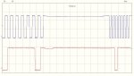
What I've recently measured with my oscilloscope is the VFD datalines, and the brushless motor's middle point. For anyone who is interested, I've attached a waveform image showing sbt vs sbi1.
 

Attachments

Last edited:
Top