Enough Amps?

Denzel

Senior Member
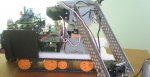
In my project I am running several applications which require 12v, these are Two DC motors which drive two high torque gearboxes connected to tank tracks and a claw run by another high torqu dc motor and 32 IR leds for my wireless video camera. Now im pretty useless when it comes to figuring out wether 12xAA is going to hack driving at most 2 motors and 32 LEDS at any one time especially when using the picaxe and other ICs its hard to tell whats in parallel and whats in series if you get my continental drift.

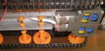
The '32 leds' is a kit from jaycar http://www.jaycar.co.nz/productView.asp?ID=KG9068&CATID=&keywords=infrared+spotlight&SPECIAL=&form=KEYWORD&ProdCodeOnly=&Keyword1=&Keyword2=&pageNumber=&priceMin=&priceMax=&SUBCATID=

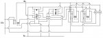
I intend on using two l293d h-bridges to run three DC motors in both directions and to turn the 32 LEDs on and off. The leds will be swithed on via the l293d via a picaxe 08m and the 3 motors will be switched on via the l293d via a picaxe 18x. Can any one help me as to wether my 12v battery pack will deliver enough current for this?

Thanks
 

manuka

Senior Member
Denzel- too lite on details mate. What are the motor ratings? "Tank tracks"- how big is the project? Your 12V pak- is this made up of 8 x 1½V AAs in series? What sort of AAs are you using -rechargeables? LEDs- running simply ( ~a few mA each) or pushing it? How long do you need to run for? Mmm -my feelings however are that you'll be in a high drain application & unlikely to get much time at all from even NiCds/NiMH

If you have no real idea then perhaps send us a project photo for an inspired guess.
 
Last edited:
You cant get 12V by using all of the 12 AA batteries.

You would need 8 (or 16 if in parallel) to get 12V

NOTE THIS IS AN ESTIMATION - AS I DON'T HAVE ACTUAL SPECS.

Doing the math:

32 LED kit - 300 ma ea (sourced from jaycar) = 300 ma
2 HIGH TORQUE DC Motor - 600ma ea (unsure) = 1200 ma
2 Picaxes (08M and 18x) 20 ma ea (unsure) = 40 ma

300 ma + 1200 ma + 40 ma = 1540 ma.

1540ma is a bit too much for AA batteries, so the answer is NO, but I can offer suggestions.

Suggestions:

- 2 x 6V lantern battery in series
- 16 x AA, 2P 6S (2 Parallel, 6 Series)
- 8 x D
- 8 x C
 

BrendanP

Senior Member
Jaycar are a rip off. Buy gell cells from a trade outlet alarm/security supply place. ie Mainline Security, Gardenvale Victoria.

Use the UC3906 to charge it. Altronics have a kit based on it.
 

manuka

Senior Member
12 V 7Ah SLA gel cells are my preferred grunty power source too. You can get them for FREE in most cities just by contacting a security firm, as critical security areas that use these as stand by batteries often replace them every 2 years-irrespective of condition. They're usually more trouble than they're worth as scrap.

I regularly get a car boot full (heavy enough to influence steering!) from a crowd here in Wellington, & drop them into deserving schools. With typical educational use (& misuse) these give YEARS of further service.
 

demonicpicaxeguy

Senior Member
i've got 5 of the things that were pulled out of electric scooters i gave them a little zap and now 4 of them are part of my ups setup and the 1 dodgy one is used to elevate one of my 3 monitors
 

Denzel

Senior Member
hmm

these 12 V 7Ah SLA gel batteries sound about right, but how big are they?

Im in wellington so where is the best place I can get a hold of one of these?

Another thing as above im using 8 AA batteries to get 12v sorry just got confused and I got the current ratings for all the motors:
so the math...

32 LED kit - 300 ma ea (sourced from jaycar) = 300 ma
2 DC Motors - 600ma ea = 1200 ma
1 high torque DC motor - 200ma
2 Picaxes (08M and 18x) 20 ma ea (unsure) = 40 ma
300 + 1200 + 200 + 40 = 1740ma 1.77A

Thanks
 
Last edited:

tarzan

Senior Member
Load

I think the weight of this particular battery is going to work against you. Depending on how fast you want your tracked vehicle to move (gearing) your motors that only draw 600ma and L293D @ 1.2A PEAK OUTPUT CURRENT are underrated for the load.
 

Denzel

Senior Member
OK,

Im using the smaller of the two batteries Stan was nice enough to give me. SLA 1.2 Ah 12v. Heres the problem:
At max eff the motors draw 680ma each so 2 x 680 = 1.36 amps this is not so much a problem for the battery but for my l293d which is driving both motors. The L293d has a max current output of 1.2 amps and as soon as I turn both these motors on, especially with the added weight of the battery and the already hefty load of the robot itself The L293d gets firey hot in about 3 seconds.

My calculation:
32 LED kit - 300 ma ea (sourced from jaycar) = 300 ma
2 DC Motors - 680ma ea (MAX EFF)= 1360 ma

300 + 1360 = 1660ma 1.66A

Is this battery going to be able to handle this current load?

As for solving my burning L293d the only solution I have come up with is to put one of the motors onto my 2nd L293d which is running the claw and turning on and off the 32 LED kit
and take the claw off and connect it to the first L293d so as apposed to 1 l293d delivering 1.36amps and the other l293d delivering 500ma (claw + 32 LED kit)
it will be:
l293d #1 680 + 300 = 980ma
l293d #2 680 + 200 = 880ma

Is this a suitable solution to my problem?
thanks
 

boriz

Senior Member
I think you are going to have trouble.

The ‘max-eff’ figure you quote is presumably for when the motor is running under light load conditions. The stall current (which is drawn every time the motor starts) is likely to be many times this figure. Potentially several amps. You will need to provide a decent overhead or your motors will not produce much torque and your silicon will over-heat.

Could you re-design? Smaller motors? Discrete H-bridge made from Power MOSFETS?
 

Denzel

Senior Member
...

What I don't understand is when using 8 AA's in series (12v) these two motors work well and everything is fine. The only problem is that when adding the 3rd motor and the 32 LED kit everything starts to go to pot. So I thought this SLA 1.2ah would be fine for this and the L293d would cope. but obviosly not...

How much current can 8 AA's in series provide?
 

Denzel

Senior Member
And to answer your question Boriz, below are some pictures of my project and as you can see its beyond the stage of a major circuit change. The 1st L293d is on the 2nd level of three. And there is quite alot of other stuff going on that makes everything a little confusing (gas, temp, light sensors, servos, radio tx/rx etc etc) There are 4 picaxe chips. 18x 2 08m's and a 14m.

Just one question. Do these SLA batteries need to be kept upright to work?
 

Attachments

papaof2

Senior Member
Unless you were using high capacity NiCd or NiMH, 8 AAs cannot provide the current that the SLA battery can; even then the internal resistance of the cells and the resistance of the cell-to-cell connections dropped the voltage applied to the load and the current through it. The L293d's weren't getting hot before because of the voltage drop in the batteries. This is one of the areas where an adjustable bench supply (with adequate capacity) allows for better testing.

For brief periods, an SLA can easily provide 20 to 50 times its rated ampere hour capacity (two 6 volt, 12 AH SLA batteries are typically used to power a 750 watt UPS) so there will be more voltage and current available and more dissipation in the L293d.

If you want to stay with a 12 volt supply, you need a higher current device to control the motors. A less efficient alternative would be an adjustable regulator (preferably switch mode) so you can set the voltage to a level the limits the dissipation in the L293d.

SLA's will work in any position; "SLA" stands for "sealed lead acid" - although many "SLA" batteries are now "AGM" (Absorbed Glass Mat) which also includes "VRLA" (Valve Regulated Lead-Acid). More details than you probably want to know are here: http://www.batterystuff.com/tutorial_battery.html

John
 

Mycroft2152

Senior Member
This is unconventional. but has worked with other driver chips. Stack 2 of the driver chips piggy back, that shopuld double your capacity.
 

boriz

Senior Member
No need to rebuild the circuit I think.

The traditional alternative to H-bridge motor control is a relay and MOSFET. You should be able to use the existing L293 outputs to drive them. A power MOSFET could easily handle several amps and the L293 would only need to provide sufficient current to drive the relay coils, far less load than the motors.
 

Rickharris

Senior Member
...as soon as I turn both these motors on, especially with the added weight of the battery and the already hefty load of the robot itself The L293d gets firey hot in about 3 seconds...

There is something else wron here because the L293 has thermal shut down protection on board - the effect is that when you draw enough current to overheat the motors stop working - This is almost instant and your 293 should NOT Get HOT. In my experience and according to the data sheet.l
 

Denzel

Senior Member
...

That exactly what I thought. According to the L293D data sheet it has a thermal shutdown. Here's what happens, The motors go on, 3 the l293d gets firey hot and the motors very quickly slow down and stop after about 4 seconds. Sorry I didn't mention that detail in the first place. But I thought the thermal shutdown would stop not only before the L293d gets hot but that the motors would stop intantly not slow to a halt of a period of 4 seconds.

In terms of solving the lack of current for the project would two of the 12v SLA batteries (1.2ah) in parallel work?

And I am looking at my options for changing the h-bridge setup and if possible still incorperating the L293D as said before earlier.

Thanks
 
Last edited:

boriz

Senior Member
Here is a diagram of what I mean:


The direction control and the on/off control can come straight from the L293.

You will of course need to duplicate this for the other motor(s).

For power switching, I usually use the P55NF06L. It can be driven by <5v on the gate and handle up to 55 Amps (TO-220 package).

EDIT: Oh yes. I forgot the diode. You should use a reverse biased diode across the Drain-Source to clamp back EMF from the motor coils.
 
Last edited:

Denzel

Senior Member
OK, that looks good Boriz thanks. I decided to try piggy back two L293Ds as suggested, the motors worked perfectly for about 20 seconds then both chips started to get very hot.
 

manuka

Senior Member
Denzel- given the nature of the (school) project & your time frame I STRONGLY suggest you just go for less demanding motors/gearing, perhaps quality Tamiya . Your current drain is so heavy at present that (even if the problems above are fixed) the beast's range may only be barely across the room before the batteries die!

This is really contrary to the "smell of an oily rag" energy age we live under- I've used PICAXEd motors that run on as little as 8mA at 1V, & even versatile steppers are around that draw less than your power hogs.
 
Last edited:

Mycroft2152

Senior Member
This is really contrary to the "smell of an oily rag" energy age we live under- I've used PICAXEd motors that run on as little as 8mA at 1V, & even versatile steppers are around that draw less than your power hogs.
Easy Stan!

For a novice that is a very misleading statement. Yes, there are some very low power steppers, but they are limitied to being used as a flag waver.

You need to match the stepper and power supply to the task at hand.

We recenrly had a posting that said -- I have a stepper and it is it runnnng on a PICAXE with a 9 volt battery, but it is not strong enough to do what I want. How do I increase its power in software. My project is due in 2 days!

We "old kids on the block" sometimes forget that the newbies take things very literally. So that those things that we take for granted are not included in our responses, causing newbies problems.

Myc
 

manuka

Senior Member
Sure- those small motors are often only proof of concept flag wavers, but it should be the "horses for courses" ethic even for electronic newbies.

I'm reminded of 1920s-30s world spanning MEGAWatt level LW radio transmitters that were bettered by hams running flea power rigs on higher freqs, & (excuse the warmongering) even WW2 era tanks & planes that were crippled by such simple oversights as poor fuel economy. Recall "brick" cell phones that barely managed ½ a day on their batteries, & early PCs that made the lights dim at bootup?


DENZEL- holiday time I believe? You may want to email me personally again for ideas. Stan
 
Last edited:

boriz

Senior Member
To get an idea of what kind of current you need to accommodate for the motors, power one straight from 12v through a multi-meter set to high current range. Then grab hold of the gears (or motor shaft, whatever) and see what the current reads when the motor is stalled. Then double it. (you should always have a good overhead). Don&#8217;t do this for more than about 2 seconds or you could cause damage. Don&#8217;t make the common mistake of using your multi-meter on low current range. You will blow it&#8217;s fuse. My meters low current range goes up to 200mA and the high range up to 10A. I&#8217;ve blown several fuses.

This is the figure you should use when designing your drive circuit. It&#8217;s unlikely to be less than 2 amps. The datasheet for the L293D says that it can handle a MAXIMUM NON-REPETETIVE current of 1.2 Amps for 100 micro-seconds. So you have the wrong motors or the wrong drive circuit.

Assuming you want to stick with the existing circuit and motors, then the relay+MOSFET add-on is one way to solve the problem. The best solution though, would be to re-build using smaller motors. Or if high torque/speed is required, re-design the driver circuit.
 

moxhamj

New Member
Denz, I've just reread the entire post and I think Boriz has been posting some great suggestions. I'd go with a mosfet and relay. The mosfet has an On resistance that is almost less than the wires that connect to it. Low resistance = not getting hot.

The maximum efficiency current draw of the motors (600mA or so) isn't a very helpful number. The motors might draw a lot less if there is no load, and they are certain to draw a lot more at startup or if you suddenly go from forward to reverse.

You can get into a bit of a "dog chasing its tail" scenario here. Too much current draw. Add a bigger battery. Bigger battery = more weight. Add bigger motors. Bigger motors needs bigger battery...

Just a quick simple test. Leave out all the motor drivers for the moment. Connect all the motors together in parallel, then to the multimeter on the 10A range as boriz says and measure the current. Measure the current with the motors unloaded (pick up the tank), then see what it is when the tank is driving up a bit of a hill. I'll bet it comes in at way over the 293 specs, but should be fine with a mosfet.

You might like to think about what happens if the motors stall. Something has to give. Does it spin its wheels? Does it strip the gears? Does the driver chip get hot and die? Do the wires get hot and melt? Does the battery explode? Does it blow the fuse (you have installed a fuse, right?). Does it trip a circuit breaker? Or my personal favourite, does it light a 60W car headlamp globe that you install in the red +ve lead as it comes out of the battery.
 
Last edited:

Denzel

Senior Member
...

Thanks for all the help. I spent last night drawing up a new drive circuit for the motors based on Boriz's suggestion and this looks like it will work. The only problem is im running out of space to put all my circuit boards hehe. And the weight of the whole project is starting to get a bit over the top.
I have until about september to finish this for the ETITO brightsparks comp, Which by the way I came 1st in Last Year for my Biped if anyone remembers helping me get through a few milestones with that project. So I have plenty of time to make mistakes and learn.

Thanks
 

geoff07

Senior Member
You might try old laptop batteries. Very high energy per kg though you have to be careful charging Li-ion. Generally some of the cells will be ok even if the battery is dud. The main problem is soldering to them as they are normally welded to thin strips and don't tin easily. I have a collection in my work-in-progress robot.
 

Wrenow

Senior Member
A warning. Do check out the specs on your motor, especially a "high torque" job. While it might seem to run just fine with a light or no load on milliamps, at stall or heafy load, the draw can be DRAMATICALLY increased.

As an example, the common surplus Mabuchi 550 might only draw 1-2 amps under light load. Stall it, and you are looking at closer to 90A. Yes, that is NOT a typo - close to ninety amps! Especially on the older ones (the newer batches seem to have a stall rating of around 86A, as I recall, though I have seen some that claim to be as low as in the mid 70's). I have seen high strand count 12 and 14 gage cable rapidly toasted at stall. And seen solder melted out of commercially made ESCs (Electronic Speed Controllers).

When you are trying to work with robotics load capable motors and controlling them, you might look into contacting your local Model Warship Combat Club, if there is one nearby as many have experrtise in this area in an extremely hostile environment (they heve to deal with water in the system as well). I seem to recall you are down under - one of the guys from http://www.ausbg.org could probably steer you the the nearest helpful maven. Sources of batteries, gearboxes, motors, etc. One thing though, most do not use differential (tank style) steering, so thewy may be less helpful in that area.

If you need sources in the US, there are also plenty, like http://www.robotmarketplace.com/store.html Lynxmotion, and the aforementioned Pololu. Keep http://dimensionengineering.com/ in mind as well.

For a wide selection of speed controllers, RCMart.com, out of Hong Kong has a variety. But beware of the various functions you want or don't want. Many that are forwards and reverse have a short pause when changing direction to save stress on the drivetrain. Some are instant (for a bot, you probably want instant). Some have time-limits on the time you spend in reverse. Some only go to, say, 75% throttle in reverse.

Good luck,

Wreno
 

Denzel

Senior Member
...

Ok. Ive set up my circuit as below...

As you can see ive used a single spdt relay (RLY #1) to turn on the 12v supply instead of the mosfet described as niether jaycar or DSE sold it or were able to suggest an equivalent component.

I set it so that the 12v is always connect to the motors so that when output 2 of the picaxe goes high the L293D will turn the 12v supply off. This is to save current when the motors are on.

My problem is this...
I set up one motor just to test the system and kept the second motor disconnected and it worked as I expected. The motor would go forward or backwards depending on what position relay 2 was in and turned off and on depending on relay 1. but as soon as I connected up the second motor and turned on the 12v. there was a bit of smoke and a copper track on my PCB between the 12v SLA connection and the 12v line burnt out????

Another thing, having never used SLA's i don't understand why when connecting a multimeter to the SLA battery it climbs steadily from 12v to 20v. ??
 

Attachments

BCJKiwi

Senior Member
Would you please review the diagram.

Customary to have + at the top and 0 at the bottom.
Can't see which is 12V plus or 0 - It appears that 12V 0 is connected to 5V+
 

manuka

Senior Member
How thick/wide is (eh- was!) this PCB copper track?! Most are good for fuse type currents of 5A, so it again strikes me that your motors are power hogs. It's akin to trying to deliver a homes high pressure & volume water supply thru' a garden hose- something will burst. In general of course such overload woes should have been explored long before a PCB was made....

12V climbing to 20V? Are you charging at the same time? Capacitors in parallel? I wish you'd contacted me during your holiday break ! Stan
 

moxhamj

New Member
Re "There was a bit of smoke and a copper track on my PCB between the 12v SLA connection and the 12v line burnt out".

See my post on page 3 - all the suggestions about "something has to give if you don't have a fuse". I guess the copper track was your fuse. Probably a good thing really as it is better than the SLA exploding.

I am going to make a suggestion but with the proviso that you please please put some sort of fuse in the line. I'd use a 12V lightbulb as a real fuse is going to keep blowing and you will get sick of buying them. You can salvage your board by running solder along the tracks to thicken them up. You can also get some bare copper wire and run them on top of the tracks with some solder. This will stop the track from exploding but then something else is going to give. Better to think about failure modes in advance rather than going through each one in turn.

If you really really can't afford a lightbulb or a fuse, use really thin hookup wire from the SLA to the board. At least it won't do too much damage when it overheats and melts.

12V climbing to 20V? If that was not while connected to a charger and was while running motors, then brilliant, you have just discovered an "over unity device" (new age speak for perpetual motion) and have singlehandedly solved all our energy problems. But if those volts are climbing while the battery is on a charger, then sadly, you may have a rather sick battery.
 
Last edited:

Denzel

Senior Member
...

I do have a fuse, but clearly it has too high a rating, i.e 5 amps and the copper track blew before the fuse did. I got a 5amp fuse because the relays i used are rated to 5 amps.

Sorry about the confusing schematic, i whipped it up in a poor attempt to show you my setup.

I changed relay 1 around so that the motors are normally off and the picaxe/ L293d turn them on. And the 12v line was exceptionally thin to start with and so ive transferred it to a track triple its size and the motors are both working a treat. The fuse isn't blowing and nothings getting hot so I guess where I go from here is to get a smaller fuse?

One issue I have is that the motors seem to be going at full pelt and faster than I want. How can I limit the speed effectively. Using a relay to turn on the 12v instead of a mosfet elimates the potential for PWM.

And as for my lovely SLA battery increasing from 12v to 20v. there is no charger or motors involved so it must be my poxy multimeter with the capabilities of a sea cucumber and the accuracy of burnt sausage. Im going shopping for a "proper" multimeter in the near future.
 
Last edited:
Top