I started a Thread on 9 Apr 2013 “EMC Testing” before attempting to get my control circuit based on a 20X2 through the UK EMC tests. People gave me helpful time and advice and I’m reporting back here after completion of the testing.
Before I get going, I’ve tried to see if there has been any discussion in between but the Forum search facility failed me. Any ideas why? I clicked ‘Search Forum’ then entered “EMC” kept the ‘Show Threads’ option, clicked ‘Search’ but got “Sorry - no matches”. That’s despite my earlier thread with “EMC” in the title. (Searching “testing” produced pages of threads)
Anyway, the controller is for controlling the 12V pump in a solar thermal system. After 4 half-day visits to my test facility, I finally had a pass. There were three areas requiring work:
I will break this up by posting on each after this initial post.
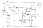
Firstly - The Original Circuit
Here is my original circuit, somewhat simplified (eg no download cable, non-relevant input removed and only one of three DS18B20 sensors shown).
Some notes:
Before I get going, I’ve tried to see if there has been any discussion in between but the Forum search facility failed me. Any ideas why? I clicked ‘Search Forum’ then entered “EMC” kept the ‘Show Threads’ option, clicked ‘Search’ but got “Sorry - no matches”. That’s despite my earlier thread with “EMC” in the title. (Searching “testing” produced pages of threads)
Anyway, the controller is for controlling the 12V pump in a solar thermal system. After 4 half-day visits to my test facility, I finally had a pass. There were three areas requiring work:
Use of pwm
Cables to DS18B20 temperature probes and separate OLED/LCD display
Vulnerability to electric shocks in supply and signal leads
Cables to DS18B20 temperature probes and separate OLED/LCD display
Vulnerability to electric shocks in supply and signal leads
I will break this up by posting on each after this initial post.
Firstly - The Original Circuit
Here is my original circuit, somewhat simplified (eg no download cable, non-relevant input removed and only one of three DS18B20 sensors shown).
Some notes:
- The control circuit PCB is in a plastic box.
- The pump has a brushless motor, it does not produce back emf. Following the April Forum discussion I removed its motor capacitor. The lead from the control box to the motor is a 20cm length of simple two-core speaker cable.
- About 4m of the same speaker cable powers the system from a 12V switched mode power supply.
- There are three DS18B20 temperature sensors, on 2m – 6m or so leads, simple 4 core ‘alarm cable’ with one core not connected to anything (3 core not available). One sensor shares a lead with the OLED for some of the way. One capacitor covered all the sensors (the OLED has its own)
- The 27 ohm resistor covered power to all the temperature sensors & OLED and was intended to protect the circuit if a short occurs in a lead or connection.
- The OLED is the AXE133Y, its lead is 3 – 5m long and its in a plastic box.
- The frequency is reduced to 4 MHz which is that used by the ReadTemp command. As I need ReadTemp that seemed to be the lowest frequency possible.