Electronic ChatterBox - Serial OLED Problems!!!

Obinna

New Member
Hi guys, I needed some help with an issue I've been having.

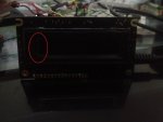
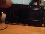
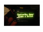
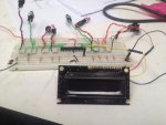
I ordered a Budget Serial OLED Module (AXE133Y) from PICAXE. I soldered it on correctly and had powered it with 4.5v to check if it was working. As it worked I decided to work on the program I need for it on my PICAXE 28x2. A few hours later I had decided to power it again this time with the serial port of the module connected to pin 14 (PORT C.3) of the PICAXE. I powered it again and this time the module did not turn on.

Fearing I had done something wrong, I ordered another one, connected it again with the same results. I do not wish to order a 3rd due to money constraints. Also the urgency of this is extremely high as I need to complete my coursework by the 4th of April. Could you please get back to me quickly with how I should proceed, thank you.

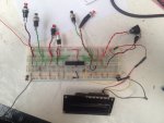
The attached items pictures of how I connected my module.
Below is the code I used.


Code:
	Init:
		SetFreq M8			'Set Clock Speed to 8Mhz'
		Let DirsB	 =%00000000	'Set Port B to Inputs'
		Let DirsC =%11111111 'Set All PORTC to Outputs'
	
	Start:
		Let OutpinsB		=%00000000		'Set All PORTB to Inputs'	
	IF pinB.7 = 1 AND pinC.7 = 1 THEN GOSUB S1andS1 'Switch 1 & Switch 1' 
	IF pinB.7 = 1 AND pinC.6 = 1 THEN GOSUB S1andS2	'Switch 1 & Switch 2'
	IF pinB.7 = 1 AND pinC.5 = 1 THEN GOSUB S1andS3 'Switch 1 & Switch 3'
	IF pinB.7 = 1 AND pinC.4 = 1 THEN GOSUB S1andS4	'Switch 1 & Switch 4'
	
	
	IF pinB.6 = 1 AND pinC.7 = 1 THEN GOSUB S2andS1 'Switch 2 & Switch 1' 
	IF pinB.6 = 1 AND pinC.6 = 1 THEN GOSUB S2andS2	'Switch 2 & Switch 2'
	IF pinB.6 = 1 AND pinC.5 = 1 THEN GOSUB S2andS3 'Switch 2 & Switch 3'
	IF pinB.6 = 1 AND pinC.4 = 1 THEN GOSUB S2andS4 'Switch 2 & Switch 4'
	
	
	IF pinB.5 = 1 AND pinC.7 = 1 THEN GOSUB S3andS1 'Switch 3 & Switch 1'
	IF pinB.5 = 1 AND pinC.6 = 1 THEN GOSUB S3andS2 'Switch 3 & Switch 2'
	IF pinB.5 = 1 AND pinC.5 = 1 THEN GOSUB S3andS3 'Switch 3 & Switch 3'
	IF pinB.5 = 1 AND pinC.4 = 1 THEN GOSUB S3andS4 'Switch 3 & Switch 4'

	IF pinB.4 = 1 AND pinC.7 = 1 THEN GOSUB S4andS1 'Switch 4 & Switch 1'
	IF pinB.4 = 1 AND pinC.6 = 1 THEN GOSUB S4andS2 'Switch 4 & Switch 2'
	IF pinB.4 = 1 AND pinC.5 = 1 THEN GOSUB S4andS3 'Switch 4 & Switch 3'
	IF pinB.4 = 1 AND pinC.4 = 1 THEN GOSUB S4andS4 'Switch 4 & Switch 4'


	S1andS1:
			   pinC.3 	= 1
			   goto S1andS1Message
	S1andS2:
			   pinC.3 	= 1
			   goto S1andS2Message
	S1andS3:
			   pinC.3 	= 1
			   goto S1andS3Message
	S1andS4:
			   pinC.3 	= 1
			   goto S1andS4Message


	S2andS1:
			   pinC.3 	= 1
			   goto S2andS1Message
	S2andS2:
			   pinC.3 	= 1
			   goto S2andS2Message
	S2andS3:
			   pinC.3 	= 1
			   goto S2andS3Message
	S2andS4:
			   pinC.3 	= 1
			   goto S2andS4Message


	S3andS1:
			   pinC.3 	= 1
			   goto S3andS4Message
	S3andS2:
			   pinC.3 	= 1
			   goto S3andS4Message
	S3andS3:
			   pinC.3 	= 1
			   goto S3andS4Message
	S3andS4:
			   pinC.3 	= 1
			   goto S3andS4Message


	S4andS1:
			   pinC.3 	= 1
			   goto S4andS1Message
	S4andS2:
			   pinC.3 	= 1
			   goto S4andS2Message
	S4andS3:
			   pinC.3 	= 1
			   goto S4andS3Message
	S4andS4:
			   pinC.3 	= 1
			   goto S4andS4Message


S1andS1Message:
    			serout 7, N2400, (254, 128)   ' Blank First Line
		      serout 7, N2400, ("Switch1	    ")
		      serout 7, N2400, (254, 192)   ' Blank Second Line
		      serout 7, N2400, ("Switch1	    ")
S1andS2Message:
    			serout 7, N2400, (254, 128)   ' Blank First Line
		      serout 7, N2400, ("Switch1	    ")
		      serout 7, N2400, (254, 192)   ' Blank Second Line
		      serout 7, N2400, ("Switch2	    ")
S1andS3Message:
    			serout 7, N2400, (254, 128)   ' Blank First Line
		      serout 7, N2400, ("Switch1	    ")
		      serout 7, N2400, (254, 192)   ' Blank Second Line
		      serout 7, N2400, ("Switch3	    ")
S1andS4Message:
    			serout 7, N2400, (254, 128)   ' Blank First Line
		      serout 7, N2400, ("Switch1	    ")
		      serout 7, N2400, (254, 192)   ' Blank Second Line
		      serout 7, N2400, ("Switch4	    ")


S2andS1Message:
    			serout 7, N2400, (254, 128)   ' Blank First Line
		      serout 7, N2400, ("Switch2	    ")
		      serout 7, N2400, (254, 192)   ' Blank Second Line
		      serout 7, N2400, ("Switch1	    ")
S2andS2Message:
    			serout 7, N2400, (254, 128)   ' Blank First Line
		      serout 7, N2400, ("Switch2	    ")
		      serout 7, N2400, (254, 192)   ' Blank Second Line
		      serout 7, N2400, ("Switch2	    ")
S2andS3Message:
    			serout 7, N2400, (254, 128)   ' Blank First Line
		      serout 7, N2400, ("Switch2	    ")
		      serout 7, N2400, (254, 192)   ' Blank Second Line
		      serout 7, N2400, ("Switch3	    ")
S2andS4Message:
    			serout 7, N2400, (254, 128)   ' Blank First Line
		      serout 7, N2400, ("Switch2	    ")
		      serout 7, N2400, (254, 192)   ' Blank Second Line
		      serout 7, N2400, ("Switch4	    ")


S3andS1Message:
    			serout 7, N2400, (254, 128)   ' Blank First Line
		      serout 7, N2400, ("Switch3	    ")
		      serout 7, N2400, (254, 192)   ' Blank Second Line
		      serout 7, N2400, ("Switch1	    ")
S3andS2Message:
    			serout 7, N2400, (254, 128)   ' Blank First Line
		      serout 7, N2400, ("Switch3	    ")
		      serout 7, N2400, (254, 192)   ' Blank Second Line
		      serout 7, N2400, ("Switch2	    ")
S3andS3Message:
    			serout 7, N2400, (254, 128)   ' Blank First Line
		      serout 7, N2400, ("Switch3	    ")
		      serout 7, N2400, (254, 192)   ' Blank Second Line
		      serout 7, N2400, ("Switch3	    ")
S3andS4Message:
    			serout 7, N2400, (254, 128)   ' Blank First Line
		      serout 7, N2400, ("Switch3	    ")
		      serout 7, N2400, (254, 192)   ' Blank Second Line
		      serout 7, N2400, ("Switch4	    ")


S4andS1Message:
    			serout 7, N2400, (254, 128)   ' Blank First Line
		      serout 7, N2400, ("Switch4	    ")
		      serout 7, N2400, (254, 192)   ' Blank Second Line
		      serout 7, N2400, ("Switch1	    ")
S4andS2Message:
    			serout 7, N2400, (254, 128)   ' Blank First Line
		      serout 7, N2400, ("Switch4	    ")
		      serout 7, N2400, (254, 192)   ' Blank Second Line
		      serout 7, N2400, ("Switch2	    ")
S4andS3Message:
    			serout 7, N2400, (254, 128)   ' Blank First Line
		      serout 7, N2400, ("Switch4	    ")
		      serout 7, N2400, (254, 192)   ' Blank Second Line
		      serout 7, N2400, ("Switch3	    ")
S4andS4Message:
    			serout 7, N2400, (254, 128)   ' Blank First Line
		      serout 7, N2400, ("Switch4	    ")
		      serout 7, N2400, (254, 192)   ' Blank Second Line
		      serout 7, N2400, ("Switch4	    ")
 

Attachments

hippy

Ex-Staff (retired)
Welcome to the PICAXE forum.

The 28X2 does not appear to have a download serial interface fitted which may lead to unreliable operation of the 28X2, may cause the program not to start.

It may also be worth starting with simpler hardware and program until you get the display working.

"serout 7" won't send serial output to C.3; you need "serout C.3" for that. Your "pinC.3=1" will however interfere with that serial data.
 

Obinna

New Member
Hi hippy, ok I I change the serout to "serout C.3" it should work? Or do I need to change the "pinC.3=1" to another code?
 

srnet

Senior Member
To troubleshoot this type of problem, best to go back to basics.

Write a simple program that does nothing but write a single line of text to the LCD, such as

serout c.3, N2400_8, (254, 128) ' Blank First Line
serout c.3, N2400_8, ("Switch1 ")

Concentrate on getting that working first.

Then you will need to revise the rest of the program, you are using gosubs but there are no returns, and the gotos should likely be gosubs with matching returns also
 

Obinna

New Member
To troubleshoot this type of problem, best to go back to basics.

Write a simple program that does nothing but write a single line of text to the LCD, such as

serout c.3, N2400_8, (254, 128) ' Blank First Line
serout c.3, N2400_8, ("Switch1 ")

Concentrate on getting that working first.

Then you will need to revise the rest of the program, you are using gosubs but there are no returns, and the gotos should likely be gosubs with matching returns also
I am not getting any kind of display showing up on my OLED module?
The whole thing is just blank.
Could it be the program I wrote before that is doing this?
 

tony_g

Senior Member
do you get the welcome message displayed on the oled when you apply just power to it?

have you made the changes that have been mentioned above? as per the manual the download circuit is a MUST and should still be left in place even when you have disconnected the download lead.

have you included the mentioned reset pin? their is an image in the getting started manuals of the absolute minimum circuit requirements for trouble free operation of any picaxe chip.

in your code you have set the port b pins as inputs and the port c pins as outputs and then in your if/then statements you are checking if port bxx and port cxx are high/low which would be looking for an input on the port c pins which were earlier set as outputs,

if i sound abrupt i appologize and thats not the intent, we just need you to confirm you have made the initial changes to the circuit as previously mentioned in posts or if you have not done so yet then make them and test again with some simple serout message commands to check the data is indeed getting through to your oled and report back so more help can be given to get this working for you.


tony
 

Obinna

New Member
do you get the welcome message displayed on the oled when you apply just power to it?

have you made the changes that have been mentioned above? as per the manual the download circuit is a MUST and should still be left in place even when you have disconnected the download lead.

have you included the mentioned reset pin? their is an image in the getting started manuals of the absolute minimum circuit requirements for trouble free operation of any picaxe chip.

in your code you have set the port b pins as inputs and the port c pins as outputs and then in your if/then statements you are checking if port bxx and port cxx are high/low which would be looking for an input on the port c pins which were earlier set as outputs,

if i sound abrupt i appologize and thats not the intent, we just need you to confirm you have made the initial changes to the circuit as previously mentioned in posts or if you have not done so yet then make them and test again with some simple serout message commands to check the data is indeed getting through to your oled and report back so more help can be given to get this working for you.


tony
Hi Tony, no there is no Welcome message when I apply power to it. I assumed this was due to the initial code i wrote to the PICAXE when I connected it.

I made the changes as mentioned above. I took the reset PIN to high to no avail.

I then tried the code that srnet suggested and still, no display on my OLED.
 

tony_g

Senior Member
ok do you have the reset pin held high with the 4.7k resistor as per the manual and can you post the current test code you are using for others to see also.
 

Obinna

New Member
Yes I've held the reset pin high with the 4.7k all to no success, still a blank display on my OLED module.

[code/]
serout c.3, N2400_8, (254, 128) ' Blank First Line
serout c.3, N2400_8, ("Switch1 ")
[/code]

This is the code srnet told me to try which I tried to no success again.
 

Obinna

New Member
Yes I've held the reset pin high with the 4.7k all to no success, still a blank display on my OLED module.

Code:
serout c.3, N2400_8, (254, 128) ' Blank First Line
serout c.3, N2400_8, ("Switch1	 ")
This is the code srnet told me to try which I tried to no success again.
 

tony_g

Senior Member
ok, how are you powering the picaxe/oled, if batteries check with a multimeter that their is still enough power for both to operate, im not sure what the minimum voltage threshold for the oled is, also maybe worth reloading the firmware for the oled onto the 18m2 backpack.

you said in your first post you initially had it working, was that just the initial preloaded welcome message or your own serout commands to the oled?
 

Obinna

New Member
ok, how are you powering the picaxe/oled, if batteries check with a multimeter that their is still enough power for both to operate, im not sure what the minimum voltage threshold for the oled is, also maybe worth reloading the firmware for the oled onto the 18m2 backpack.

you said in your first post you initially had it working, was that just the initial preloaded welcome message or your own serout commands to the oled?
My battery pack is 4.5V but I also tried a 5V power supply and it didn't work.
When I said it was working, I meant the preloaded welcome message which stopped appearing after I had connected it to said picaxe pin in the first post.

Also how would I reload the firmware for the 18M2?
 

tony_g

Senior Member
the oled backpack should have a socket connector to plug the picaxe download cable into and reload this basic file:

Code:
; AXE133 Serial LCD/OLED using PICAXE-18M2
; Emulates basic serial operation of the popular AXE033 module
; CPS, May 2011
; v2 18/01/2012

#picaxe 18M2

; ********************************************
; Note you must uncomment just one of these two options
; depending on whether you have an LCD or OLED module
#define use_OLED
;#define use_LCD
; ********************************************


; Supported Commands
; 0-7, 8-15	CGRAM characters
; 16-252	normal ASCII characters, according to selected character map table
; 253, X	display 16 character pre-saved message from EEPROM memory, X can be 0-15
; 254, X	LCD command, X can be 0 to 255 
; 255, X	control outputs C.2, C.1, C.0 (via lower 3 bits of X)
;		So, if using a backlit LCD with the active low transistor driver
;		on output C.2, then 255,%000 switches backlight on and 255,%100 switches off


#define use_welcome	; display the welcome message upon power up
symbol line_length = 16	; change to 20 for displays with 20 character lines

symbol baud = N2400_16	; Serial baud rate 2400,N,8,1. Note main program runs at 16MHz

symbol spare0 	= C.0 ; spare output 0
symbol spare1 	= C.1 ; spare output 1
symbol spare2 	= C.2 ; spare output 2 (or optional backlight)
symbol backlight 	= C.2 ; optional backlight control for backlit LCDs, active low
symbol RX		= C.5	; serial receive pin
symbol enable 	= C.6	; LCD enable
symbol rs 		= C.7	; LCD RS 


; LCD data pins are on B.0 to B.7

; Store the 16 character user defined messages in EEPROM data memory
; First two messages are optionally used as welcome message

; If using a display with 20 characters you will need to edit 
; the start addresses to be multiples of 20 (currently at 16) 
; and add 4 characters to each message.
; Please remember 4 line displays always use the strange 1-3-2-4 layout.

#ifdef use_OLED		
EEPROM $00, ("  Serial OLED   ") 	; store msg in the EEPROM memory
#else
EEPROM $00, ("   Serial LCD   ") 	; store msg in the EEPROM memory
#endif


EEPROM $10, (" www.picaxe.com ") 	; store msg in the EEPROM memory

EEPROM $20, ("This is msg 2   ") 	; store msg in the EEPROM memory
EEPROM $30, ("This is msg 3   ") 	; store msg in the EEPROM memory
EEPROM $40, ("This is msg 4   ") 	; store msg in the EEPROM memory
EEPROM $50, ("This is msg 5   ") 	; store msg in the EEPROM memory
EEPROM $60, ("This is msg 6   ") 	; store msg in the EEPROM memory
EEPROM $70, ("This is msg 7   ") 	; store msg in the EEPROM memory
EEPROM $80, ("This is msg 8   ") 	; store msg in the EEPROM memory
EEPROM $90, ("This is msg 9   ") 	; store msg in the EEPROM memory
EEPROM $A0, ("This is msg 10  ") 	; store msg in the EEPROM memory
EEPROM $B0, ("This is msg 11  ") 	; store msg in the EEPROM memory
EEPROM $C0, ("This is msg 12  ") 	; store msg in the EEPROM memory
EEPROM $D0, ("This is msg 13  ") 	; store msg in the EEPROM memory
EEPROM $E0, ("This is msg 14  ") 	; store msg in the EEPROM memory
EEPROM $F0, ("This is msg 15  ") 	; store msg in the EEPROM memory

;initialise LCD
init:
	gosub LCD_init 		; initialise LCD

; display welcome message if desired
#ifdef use_welcome	
	let b1 = 0			; message 0 on top line
	gosub msg			; do it

	low rs			; command mode
	let pinsB = 192		; move to line 2, instruction 192
	pulsout enable,1  	; pulse the enable pin to send data.
	high rs			; character mode again
	
	let b1 = 1			; message 1 on bottom line
	gosub msg			; do it
#endif		
		
; main program loop, runs at 16MHz

main:

	serin RX,baud,b1			; wait for the next byte

	; NB keep character mode test as first item in this list to optimise speed
	if b1 < 253 then
		let pinsB = b1 		; output the data
		pulsout enable,1  	; pulse the enable pin to send data.
		goto main			; quickly loop back to top
	else if b1 = 254 then
		low rs 	     		; change to command mode for next character
		serin RX,baud,b1		; wait for the command byte
		let pinsB = b1 		; output the data
		pulsout enable,1  	; pulse the enable pin to send data.
		high rs			; back to character mode
		goto main			; quickly loop back to top
	else if b1 = 253 then
		serin RX,baud,b1		; wait for the next byte
		gosub msg			; do the 16 character message
		goto main			; back to top
	else ; must be 255
		serin RX,baud,b1		; wait for the next byte
		let pinsC = b1 & %00000111 | %10000000
						; output the data on C.0 to C.1, keep RS high
		goto main			; back to top
	end if


; power on LCD initialisation sub routine
LCD_init:
	let dirsC = %11000111	; PortC 0,1,2,6,7 all outputs
	let dirsB = %11111111	; PortB all outputs


#ifdef use_OLED
	; Winstar OLED Module Initialisation
	; according to WS0010 datasheet (8 bit mode)

	pause 500 			; Power stabilistation = 500ms

	; Function set - select only one of these 4 character table modes
	;let pinsB = %00111000 	; 8 bit, 2 line, 5x8 , English_Japanese table
	let pinsB = %00111001 	; 8 bit, 2 line, 5x8 , Western_European table1
	;let pinsB = %00111010 	; 8 bit, 2 line, 5x8 , English_Russian  table
	;let pinsB = %00111011 	; 8 bit, 2 line, 5x8 , Western_European table2
	
	pulsout enable,1  	; 
		
	let pinsB = %00001100	; Display on, no cursor, no blink
	pulsout enable,1 	

	let pinsB = %00000001 	; Display Clear
	pulsout enable,1
	pause 7			; Allow 6.2ms to clear display

	setfreq m16			; now change to 16Mhz

	let pinsB = %00000010 	; Return Home
	pulsout enable,1

	let pinsB = %00000110 	; Entry Mode, ID=1, SH=0
	pulsout enable, 1


#else	
	; Standard LCD Module Initialisation
	pause 15 			; Wait 15ms for LCD to reset.

	let pinsB = %00110000 	; 8 bit, 2 line
	pulsout enable,1  	; Send data by pulsing enable
	pause 5 			; Wait 5 ms
	pulsout enable,1 	 	; Send data 48 again
	pulsout enable,1  	; Send data 48 again
	
	setfreq m16			; now change to 16Mhz

	let pinsB = %00111000 	; LCD  - 8 bit, 2 line, 5x8  
	pulsout enable,1
			
	let pinsB = %00000001	; Clear Display
	pulsout enable,1 	
	pause 8			; 8 = 2ms at 16MHz
	
	let pinsB = %00000010 	; return home
	pulsout enable,1

	let pinsB = %00000110	; Entry mode
	pulsout enable,1 	
	pause 1			

	let pinsB = %00001100	; Display on, no cursor, no blink
	pulsout enable,1 	
#endif
	
	high rs			; Leave in character mode
	return


; display message from EEPROM sub routine
; message number 0-15 must be in b1 when called
; uses (alters) b1, b2, b3, b4
msg:
	let b2 = b1 & %00001111 * line_length
						; EEPROM start address is 0 to 15 multiplied by 16
	let b3 = b2 + line_length - 1 ; end address is start address + (line_length - 1)
	for b4 = b2 to b3			; for 16 times
		read b4,b1			; read next character from EEPROM data memory into b1
		let pinsB = b1 		; output the data
		pulsout enable,1  	; pulse the enable pin to send data.
	next b4				; next loop
	return
	
; Check end user has defined just one type of display
#ifndef use_OLED
#ifndef use_LCD
#error "Oops - no OLED / LCD type defined at top of program!"
#endif
#endif

#ifdef use_OLED
#ifdef use_LCD
#error "Oops - both OLED / LCD types defined at top of program!"
#endif
#endif
as long as the display still shows the welcome message then try again sending some serout commands from the 28x2 but maybe try using a different pin and see if you still have communication problems
 

Obinna

New Member
Hi again Tony, copied and pasted the code into the programming editor as you said but when it finished programming, I get this brief thin line split in two that comes up then dims away quickly. hopefully you can see it in the picture I've attached, its inside the red oval.

Optimized-photo red.jpg
 

Rick100

Senior Member
I would check the power connections from the breadboard to the display. Make sure you have at least 4.5 volts measured on the display board. You could have a bad connection causing a voltage drop. It sure looks like a power problem.
 
Okay. Everytime I had a problem with the ax33 it.was always something I missed in the pre,construction of the lcd. One. Out goes to in and in to out. When you apply pwr to the lcd it.normaly starts with garbly gook for.a.sec. in serial mode make sure your connecting directly to.the chip pins and not via anything else. With project boards you have to solder directly to chip inputs.
The 0v and + can connect to your power rail. If using 4.5 pwr supply youll have lil problems. Also most those lcdshave a spot to mount an led that lets you know its powered and timing. Usually its a hardware error is what im saying
 

Obinna

New Member
I would check the power connections from the breadboard to the display. Make sure you have at least 4.5 volts measured on the display board. You could have a bad connection causing a voltage drop. It sure looks like a power problem.
Hey Rick, I tried raising the voltage to 5 on my power supply and got this random dotted line in the top segment of the display as is evident in the video.
[video=youtube_share;km7VX52hdLE]http://youtu.be/km7VX52hdLE[/video]
I then tried 4 battries using a battery pack which was 6.1 volts and got the same similar 2 lines that I had in my previous image post.
Optimized-securedownload.jpg

Still no real display that says "Serial OLED" and whatever the rest was.
 
Last edited:

Technical

Technical Support
Staff member
Its extremely unlikely that 2 separate displays will become faulty without some external influence / incorrect assembly.

Please can you post a photo of the back of the AXE133Y, showing where the wires are connected.
Also a close up of the assembly/soldering.

Also that type of power supply is not ideal for testing, and could easily supply a voltage that would damage the module.
Please use 3xAA cells whilst troubleshooting, it just removes one more thing out of the long 'possible fault' list.
 

Obinna

New Member
Hey guys, I decided to buy a new one as my deadline is in 2 days and need to start construction on my project ASAP!!!

This time I was wondering if you guys could help me with what I need to do.

I basically need the display to change, every time I press a combination of 2 switches.
 

JimPerry

Senior Member
Two kits not working - you are probably doing the same thing wrong in assembly. Where in the UK are you? I have 2 OLED displays that work :confused:
 

flyingnunrt

Senior Member
You can simulate the OLED in picaxe editor 6.0.6.2 Have you used it?
That will verify that your code is working as expected.
There are some settings to be configured in the options menu before it will work.
 
Last edited:

Obinna

New Member
You can simulate the OLED in picaxe editor 6.0.6.2 Have you used it?
That will verify that your code is working as expected.
There are some settings to be configured in the options menu before it will work.
Oh okay, what settings should I change, this sounds like a good idea.
 

Obinna

New Member
File/Options/Simulation/Serial LCD-OLED module and select what you have connected to which pin.
Ok thanks I've found it. Was wondering if anyone knew or could show me the code in order for the message to change when I press 2 switches on after another?
 

Obinna

New Member
Hey guys so I have my new OLED and this one works. I wanted to know how you would change the predefined message on the screen.
 

Obinna

New Member
Hey guys so I have my new OLED and this one works. I wanted to know how you would change the predefined message on the screen.
Actually don't worry I've done it :). What I really need to know how to do is make the display change every time a switch is pressed that is connected to one of the output pins. I have a PICAXE 28x2 if this helps?

I'm guessing it involves the use of subroutines, please could I have feedback as I am a beginner with thisChatterBox.png
 

oracacle

Senior Member
it will dpend on what port you have the switches connected to

heres a quick exmple to scan 2 input (port c, input 0 and 1), make sure you have all the pins on at least that bus tied low and portection resitors on each of the used pins

Code:
[color=Blue]let [/color][color=Black]dirc [/color][color=DarkCyan]= [/color][color=Navy]%00000000          [/color][color=Green]'set all port c pins to inmputs[/color]

[color=Black]main:
      [/color][color=Blue]if [/color][color=Purple]pinc.0 [/color][color=DarkCyan]= [/color][color=Navy]1 [/color][color=Blue]then
            [/color][color=Green]'do stuff here
      [/color][color=Blue]end if
      
      if [/color][color=Purple]pinc.1 [/color][color=DarkCyan]= [/color][color=Navy]1 [/color][color=Blue]then
            [/color][color=Green]'do stuff here
      [/color][color=Blue]end if
      
      goto [/color][color=Black]main[/color]
 

Obinna

New Member
it will dpend on what port you have the switches connected to

heres a quick exmple to scan 2 input (port c, input 0 and 1), make sure you have all the pins on at least that bus tied low and portection resitors on each of the used pins

Code:
[color=Blue]let [/color][color=Black]dirsc [/color][color=DarkCyan]= [/color][color=Navy]%00000000          [/color][color=Green]'set all port c pins to inmputs[/color]

[color=Black]main:
      [/color][color=Blue]if [/color][color=Purple]pinc.0 [/color][color=DarkCyan]= [/color][color=Navy]1 [/color][color=Blue]then
            [/color][color=Green]'do stuff here
      [/color][color=Blue]end if
      
      if [/color][color=Purple]pinc.1 [/color][color=DarkCyan]= [/color][color=Navy]1 [/color][color=Blue]then
            [/color][color=Green]'do stuff here
      [/color][color=Blue]end if
      
      goto [/color][color=Black]main[/color]
So if I was to connect a switch (using a 10k resistor for the bottom part) across C.1 and C.0 then would the text in the speech marks display on the OLED if the OLED's serial port was connected to B.7?

Code:
let dirsc = %00000000          'set all port c pins to inmputs

main:
      if pinc.0 = 1 then serout B.7,N2400,("Switch 1 Pressed")
            'do stuff here
      end if
      
      if pinc.1 = 1 then serout B.7,N2400,("Switch 2 Pressed")
            'do stuff here
      end if
Also what resistor do you recommend as a protection?
 
Last edited:

oracacle

Senior Member
your code will generate syntax error, PE6 even show the error in code with jacked red line in the the end if statements.

Code:
[color=Blue]let [/color][color=Purple]dirsc [/color][color=DarkCyan]= [/color][color=Navy]%00000000          [/color][color=Green]'set all port c pins to inmputs[/color]

[color=Black]main:
      [/color][color=Blue]if [/color][color=Purple]pinc.0 [/color][color=DarkCyan]= [/color][color=Navy]1 [/color][color=Blue]then 
            serout B.7[/color][color=Black],[/color][color=Blue]N2400[/color][color=Black],[/color][color=Blue]([/color][color=Red]"Switch 1 Pressed"[/color][color=Blue])
      end if
      
      if [/color][color=Purple]pinc.1 [/color][color=DarkCyan]= [/color][color=Navy]1 [/color][color=Blue]then 
            serout B.7[/color][color=Black],[/color][color=Blue]N2400[/color][color=Black],[/color][color=Blue]([/color][color=Red]"Switch 2 Pressed"[/color][color=Blue])
      end if[/color]
and whe you say accross c.0.and c.1 what do you mean ar you a DPST switch, or is there 2 switches, nomrally the switch would go from +v to pin tied low with a 10k with a 1 k protection resistor between the switch and pin.

you should read manual 3
http://www.picaxe.com/Getting-Started/PICAXE-Manuals/
see page 26, you will need 2 of those circuit, one for each switch.
 

Obinna

New Member
your code will generate syntax error, PE6 even show the error in code with jacked red line in the the end if statements.

Code:
[color=Blue]let [/color][color=Purple]dirsc [/color][color=DarkCyan]= [/color][color=Navy]%00000000          [/color][color=Green]'set all port c pins to inmputs[/color]

[color=Black]main:
      [/color][color=Blue]if [/color][color=Purple]pinc.0 [/color][color=DarkCyan]= [/color][color=Navy]1 [/color][color=Blue]then 
            serout B.7[/color][color=Black],[/color][color=Blue]N2400[/color][color=Black],[/color][color=Blue]([/color][color=Red]"Switch 1 Pressed"[/color][color=Blue])
      end if
      
      if [/color][color=Purple]pinc.1 [/color][color=DarkCyan]= [/color][color=Navy]1 [/color][color=Blue]then 
            serout B.7[/color][color=Black],[/color][color=Blue]N2400[/color][color=Black],[/color][color=Blue]([/color][color=Red]"Switch 2 Pressed"[/color][color=Blue])
      end if[/color]
and whe you say accross c.0.and c.1 what do you mean ar you a DPST switch, or is there 2 switches, nomrally the switch would go from +v to pin tied low with a 10k with a 1 k protection resistor between the switch and pin.

you should read manual 3
http://www.picaxe.com/Getting-Started/PICAXE-Manuals/
see page 26, you will need 2 of those circuit, one for each switch.
I mean with 1 leg of switch going to V+ and the other one going to ground via a 10k resistor also the 1k resistor inbetween these two components will go to the corresponding pin.

Also how do I fix the code that is coming up in red? It works fine on the simulator.
 

oracacle

Senior Member
it should work fine, its a waste of time

also missed to goto main to generate a continuos loop, this should go at the end of the program. you could also use do...loop

sounds like you are getting there, as long as you have something that looks like the manual for the switches then you should be fine

you could use this
Code:
[color=Blue]let [/color][color=Purple]dirsc [/color][color=DarkCyan]= [/color][color=Navy]%00000000          [/color][color=Green]'set all port c pins to inmputs[/color]

[color=Black]main:
      [/color][color=Blue]do
      if [/color][color=Purple]pinc.0 [/color][color=DarkCyan]= [/color][color=Navy]1 [/color][color=Blue]then
            serout B.7[/color][color=Black],[/color][color=Blue]N2400[/color][color=Black],[/color][color=Blue]([/color][color=Red]"Switch 1 Pressed"[/color][color=Blue])
      end if
      
      if [/color][color=Purple]pinc.1 [/color][color=DarkCyan]= [/color][color=Navy]1 [/color][color=Blue]then 
            serout B.7[/color][color=Black],[/color][color=Blue]N2400[/color][color=Black],[/color][color=Blue]([/color][color=Red]"Switch 2 Pressed"[/color][color=Blue])
      end if
      loop[/color]
or this
Code:
[color=Blue]let [/color][color=Purple]dirsc [/color][color=DarkCyan]= [/color][color=Navy]%00000000          [/color][color=Green]'set all port c pins to inmputs[/color]

[color=Black]main:
      [/color][color=Blue]if [/color][color=Purple]pinc.0 [/color][color=DarkCyan]= [/color][color=Navy]1 [/color][color=Blue]then
            serout B.7[/color][color=Black],[/color][color=Blue]N2400[/color][color=Black],[/color][color=Blue]([/color][color=Red]"Switch 1 Pressed"[/color][color=Blue])
      end if
      
      if [/color][color=Purple]pinc.1 [/color][color=DarkCyan]= [/color][color=Navy]1 [/color][color=Blue]then 
            serout B.7[/color][color=Black],[/color][color=Blue]N2400[/color][color=Black],[/color][color=Blue]([/color][color=Red]"Switch 2 Pressed"[/color][color=Blue])
      end if
      goto [/color][color=Black]main[/color]
or a fair amount of other variations that will do the same thing
 
Top