Electret Mirophone to Servo Interface

sailgene

Member
Hello.

I've been studying various animatronic projects and would like to set up a servo to respond to an adc input via a microphone. The idea would be to move a "jaw" up and down proportionately to the volume or length of time a voice was transmitted via a microphone. In other words, a long duration sound would move the servo to one end and hold it there (for the duration of the sound), a short sound would only move the servo slightly.

I've seen the excellent circuit to amplify an Electret Mic for the input side of the Picaxe but was wondering if the output to a servo can be controlled to the extent I'm looking for?

Hope I'm not sounding too stupid here.

Thanks. :)
 

hippy

Ex-Staff (retired)
Should be possible. It will be a loop, similar to ... Is sound present ? No, reset servo to start position, Yes, move it along a bit, Repeat.
 

Marcwolf

Senior Member
Hi Sailgene

I found these on a site and have brought 2 for experimentation. I plan to use them, in an ear movement rather than a jaw

http://www.dfrobot.com/index.php?route=product/product&keyword=microphone&category_id=0&description=1&model=1&product_id=83ine

What they do is amplify the sound volume and convert to a voltage that you can use with ADC pin. You can vary the gain thus the output voltage.
From there you can playaround with the values to drive the servo.

This is strictly for volumn, nothing to do with frequency. Frequency is a bit more complex but this chip should help there

http://www.littlebirdelectronics.com/products/Graphic-Equalizer-Display-Filter-MSGEQ7.html

What this does is to take a sound sample and split it into 8 freq bands. These can be read by pulsing a output pin and then reading the ADC value on another. The higherthe voltage means the louder that frequency range is. As it is purely a pulse/read interface a very simple Picaxe can handle it.

Hope this helps
Dave
 
Last edited:

sailgene

Member
Thanks guys. Looking forward to trying this out. I appreciate the link to the analog sound sensor (that will save some work).
 

Marcwolf

Senior Member
An Addendum to the DF Robot Sound Sensors. They seem to be just an amplifier.
There is talk on some forums of adding a diode to rectify the output to DC and then a 1k resistor and a 0.01uf capacitor filter to smooth the fluctuations.

Here is the link http://www.arduino.cc/cgi-bin/yabb2/YaBB.pl?num=1279922702


Another method is to use a 'cheap' envelope follower. What you can do is to put a LED on the output of the Sound Sensor and an Light Dependant Resistor on the PicAxe analogue. The response of the LDR should muffle out the transients.


Hope this helps
Dave
 
Last edited:

fritz42_male

Senior Member
Why not use the Sparkfun sound sensor? - its designed to work with an Arduino so it should be just a matter of code changes. It's adequately documented too with example code, schematics, specs and even a project site that has an example sound to light setup.

http://www.sparkfun.com/products/9964

For mouth movement, you may want to build in variable delay and amplitude control. You don't want the mouth to 'chatter'

A purely discrete solution I picked up for driving motor driven mouths on props, used a 555 circuit to put in a delay to stop chatter. Designer was Jim Kadel (nice guy)

Below is a link to his first circuit design without the 555 delay.

http://home.rica.net/jimk/projects/servo/index.htm
 
Last edited:

sailgene

Member
Ohhhh the humanity

Thanks, guys for the tips and links. Right now, I'm just dealing with total, and I mean TOTAL frustration in trying to control a servo. Thought it would be simple but in reading various posts, it seems that between the need for capacitors, various pause rates, voltage fluctuations, etc., that I've gone swimming over my head.

I've tried using .001 and .01 ceramic caps at the picaxe (20M) V and 0 posts, placing diodes at the power source to the servo, using simple servo commands, differing pause rates, do-loops, and still no servo control. I've copied various command suggestions figuring they would work - still nothing. I use separate power sources to the pic and servo but to no avail. I've tried more than one pic and more than one servo. I don't have a scope to check out what's happening I do bellieve tht the chip keeps resetting but with a separate power source, I'm surprised this would happen. All I can say is that either the 20M is a poor choice for servo control or that I'm an idot - possible most weight on the latter.

My next attempt will be to try a 555 circuit just to see if I can get something working. Ohhhh the humanity.....

Sorry for the rant but I went for a Picaxe solution because the programming seemed so easy. If only.....
 

MartinM57

Moderator
Simplify it all down - just flash a LED (and a resistor) with simple pause commands in a loop. No servos, ADCs etc

Put
Code:
pause 2000
sertxd("Started", CR, LF)
at the top of the code and press F8 after you've downloaded the program to get the terminal window. If you get more than one "Started" message the PICAXE is resetting.

Post code, pictures, schematics etc - otherwise we are all guessing...

No need for a 555 yet :D
 

sailgene

Member
Thanks so much. Ran the Sertxd program and all seemed well. Then put a servo through a simple test and of all things, it worked too - finally!

Just wondering if you know, using Servo 75 and Servo 220 is not getting much more than 90 degrees. I get a buzz over 220 but haven't tried something under 75. Are some servos that limited or is it possible that numbers less than 75 will work?

Thanks again. Phew!
 

eclectic

Moderator
sailgene.

Look at Martin's question in post #9

"Post code, pictures, schematics etc - otherwise we are all guessing..."

e
 

sailgene

Member
Project Board Assist

Welllll, everything works great, as long as I'm using the Project Board. But if I place the setup on a breadboard, I'm getting some serious timing delays. This simple program below was to test the program with a variable (4). I was using a small capacitor across the V+ and V0 of the Picaxe.

Simple Code:

Servo 7,60
Pause 2000
Let B0=4

Main:

If B0=4 then Open
Open:
Servo 7,150
Pause 4000
Goto Main

Does anyone know if the Darlington Driver on the Project Board has some internal capacitance and/or diodes which could be assisting with the PWM of the Picaxe?
 

eclectic

Moderator
Welllll, everything works great, as long as I'm using the Project Board. But if I place the setup on a breadboard, I'm getting some serious timing delays. This simple program below was to test the program with a variable (4). I was using a small capacitor across the V+ and V0 of the Picaxe.

Simple Code:

Servo 7,60
Pause 2000
Let B0=4

Main:

If B0=4 then Open
Open:
Servo 7,150
Pause 4000
Goto Main

Does anyone know if the Darlington Driver on the Project Board has some internal capacitance and/or diodes which could be assisting with the PWM of the Picaxe?
Have I missed something?
Which project board?

And, if it works on the
Project Board,
but NOT on your breadboard, then
check your BB circuit.

And now please POST your BB circuit
and a couple of Hi-Res photo's.

e
 

Marcwolf

Senior Member
When working with servo's I find it is a good idea to run some test programs to find the range of the servo.. With the more expensive digitial servo's you can program the limits.

With the simpler analogue servo's their range can vary from product to product. Just run a simple program to move the servo from one end of it's range to the other. And reduce the range if the servo buzzes at either end of its movement.

Re the 555 timer, it's easy to build this into code and it's called Hysteresis.
I'll try and pseudo code it as I'm not at my development machine.

Code:
Init:
  W5 = 90
  W6 = 90
  W7 = 90
  Set Servo to W5
Main:
  Take a Reading W5
  If W5 > (W6 + 5) then
    Set Servo to W5
    W6 = W5
    Goto Main
  End If 
  If W5 < (W7 - 5) then
     Set Servo to W7
     W7 = W5
     Goto Main
  End If 
  ' no servo chage
  Goto Main
This code can be simplfied. What it does is to take a reading. If the reading is only a small difference (5) between the previous reading the do nothing.
If the new reading is a larger difference between the two reading then set the servo to the new reading and save the new reading for comparison.

This will help stop the chatter.

Take Care
Dave
 

sailgene

Member
Per your request

Hello again.

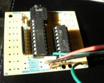
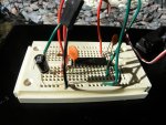
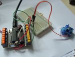
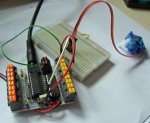
I've attached a couple of pics (compressed and may not be readable) to answer some questions. I've got high res. pics but the website restricts pics over 20kb.

Once again, I'm using a Picaxe 20M with a project board (AXE 118). The Servo works perfectly with it. I have the signal wire coming off of Pin 7 and a ground wire coming off of a ground location ("out 7") on the board. I can't tell if the Darlington Driver on the board is even in play. The board is powered by a battery pack and the servo is powered by a 5 volt regulated supply. The servo swings smoothly back and forth as per the programming. By the way, I've experimented long enough to eliminate chattering by trial and error relative to maximum pivot movement.

On my bread board, I'm using separate power sources ((2) 5 volt regulated supplies) and combining their ground wires. I've got a .1uF Ceramic Cap spanning the V+ and V0 pins on the Picaxe, a .1uF Ceramic Cap spanning the V+ and V0 connections for the Servo Motor connections as well as a 47uF Cap on the same V+ & V0 points for the Servo Motor. I don't have any caps on the Servo signal wire. There is also a 330 ohm Resistor between Pin 7 and the signal wire. With this setup, I get minimal, jerky movement of the servo. The caps don't seem to affect it as I've tried this with and without their buffering.

The current code I'm using is:

Code:
SERVO 7,70

START:
FOR B0= 70 TO 200 STEP 5
SERVO 7,B0
PAUSE 30
NEXT B0
PAUSE 1000

FOR B0=200 TO 70 STEP -5
SERVO 7,B0
PAUSE 30
NEXT B0
PAUSE 1000

GOTO START
So that's about it. I'm really frustrated. If there's a way to use larger file sizes for jpeg docs, I'll resubmit them. Thanks again for any help.
 

Attachments

Last edited:

sailgene

Member
Darlington Driver

This is just an FYI. I've played around with the AXE118 board and have discovered that the Darlington Driver is definitely making the difference in the circuit working. I'm grounding pin (or leg) 11 of the Driver and that seems to work. Without that connection or without the Driver, the Servo does nothing. So it looks like maybe it's amplifying the Picaxe signal? Anyway, that the latest....
 

sailgene

Member
ULN Chip

Actually, I did remove the chip to see what would happen and the Servo stopped working. So the Chip is doing something. Perhaps the internal diode or the boosting of the signal via a transistor?
 

eclectic

Moderator
re post #15
"I have the signal wire coming off of Pin 7 and a ground wire coming off of a ground location ("out 7") on the board."
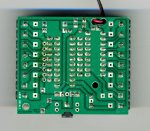
and the AXE118 photo:

The "out7 " is NOT a gnd.

The gnd is 0V near the top right of the board

e
 

sailgene

Member
Hello E,

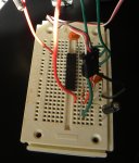
The top of the chip is to the right, using red (far side) for +V and green (near side) for ground. Pin 7 (out) is on the left end (bottom of chip - nearest camera) and is hard to see. A 330 ohm resistor is coming off of Pin 7 and the Cap is kinda hiding that connection.

You should understand that I know the input and output pins of this chip and have successfully programmed it, as well as the 08M, on simpler tasks such as standard on/off routines and timing routines.

I've attached another photo (different angle) which may help visualize the BB layout (top of chip is far end with V+ and Ground connections). However, in this shot, the servo connector blocks out some of the setup.
 

Attachments

sailgene

Member
Schematic

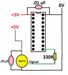
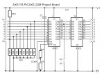
I've attached a crude schematic layout of the circuit, omitting the 47uF cap I'd also placed over the Servo "header". Hope this helps.
 

Attachments

sailgene

Member
Success!

Well,

I found a website advertising an 08M schematic to control 3 servos. The schematic included a 33uF Tantalum Capacitor located between the positive side to the Servo Power and Ground. So I pulled out a 33uF Electrolytic Capacitor (no idea what a "tantalum" cap is) just to see what would happen.

If works! This was WITHOUT the ceramic caps between the positive and negative sides of the chip.

The website is: http://www.robotshop.ca/content/PDF/picaxe-08m-servo-driver-axe024-user-guide.pdf if anyone is interested.

Thanks again for all the help on this. I do wonder if the manual shouldn't be a little more straight forward on the typical servo hookup.
 

Marcwolf

Senior Member
One of the problems with servo's is that they are electrically noisy and power hungry. One needs a very good power source to work with them effectively

The 33uf would be helping a little on the transients as well as filtering out some of the motor noise.

My current project where I am powering both microcontrollers and servos - I have 2 x 7.2v to 5v battery convertors. One for the servo's and the other for the electronics. That way I can try and keep electrical noise to a minimum.

Dave
 

sailgene

Member
Separate Power Sources

Hi Dave.

Funny thing - for all my problems trying to get my breadboard to work with servos, I've been using separate power sources continuously. But for whatever reason, I've had the worst luck. Still wondering if the 20M chip is flakey.

But I'm finally getting it to work, with some hiccups on startup - possibly due to the cap charging.

My next goal is to get a servo to respond to an input pin going high. I've got it to work (sort of) but after a few decent responses, it stops working.

My eventual goal is to control servos with serial inputs with digital and/or analog pin inputs on a separate chip.

Thanks again for your help - and patience.

Gene
 

fritz42_male

Senior Member
Just FYI, I started a project for a low cost Halloween Prop controller based on the 08M project board - nothing sophisticated but all the connectors were 'servo type' with gnd, +V and signal brought out. Aim was to make a sub$10 controller.

Never finished the PDF but got a few people using them for various things including random servo movement, PIR activated servos, Fog machine timers etc.

The nice thing about the 3 pin servo connector is it works well for inputs and outputs. e.g. A 10K Pot, switch, LED, PIR, Servo, IRL520 all work. Lately started plugging 'daughter' boards into it.

Unfinished PDF is here:

http://www.ipprofessional.com.au/VLC Servo Controller.pdf
 

hippy

Ex-Staff (retired)
Funny thing - for all my problems trying to get my breadboard to work with servos, I've been using separate power sources continuously. But for whatever reason, I've had the worst luck. Still wondering if the 20M chip is flakey.
It's extremely unlikely the 20M chip is flakey. There are certain constraints on what can be done with servos ( especially when trying to do some things in conjunction with running those servos ), power supply requirements can be quite demanding, and electrical noise can be an issue.

In most cases problems are either in trying to do something which conflicts with what servo control can do or electrical issues.
 

eclectic

Moderator
I'm still puzzled by the circuit
you described in post #15.
So, I tried to reproduce it,
and used your program from post #12.

Code:
SERVO 7,70

START:
FOR B0= 70 TO 200 STEP 5
SERVO 7,B0
PAUSE 30
NEXT B0
PAUSE 1000

FOR B0=200 TO 70 STEP -5
SERVO 7,B0
PAUSE 30
NEXT B0
PAUSE 1000

GOTO START
With the servo's "gnd" from Out7,
only a faint buzzing.

With the servo connected to
a 0V, the horn rotates forward and back.

e
 

Attachments

sailgene

Member
Ground

E,

The servo's ground is not from "out 7". It's on the common ground rail (right side of board). A green wire is used for the signal wire (coming from "out 7")which you may be confusing with a ground wire. I didn't have any white or yellow wire to hook to help with color coding.
 

sailgene

Member
By the way, E, I also had good luck running my servo directly from the Picaxe board. Although my board looks slightly different than yours. But that's why I mentioned the issue of the Darlington Driver on the board. For whatever reason, it just seems to work fine.

But when I transferred the chip to the breadboard (i.e. sans picaxe board), that's when the problems began. Post #21 shows the breadboard circuit I set up. Maybe I messed up with the capacitor locations? Anyway, it seems to work okay now, although I still get some hiccups on the servo before it begins to follow the programming.

But when trying to add a pin-high command to tell the servo to move, it only works intermittently. I'm using a 10K resistor to pull the pin down to ground but still, the chip doesn't seem to like to answer to the pin-high command more than a few times.
 

eclectic

Moderator
E,

The servo's ground is not from "out 7". It's on the common ground rail (right side of board). A green wire is used for the signal wire (coming from "out 7")which you may be confusing with a ground wire. I didn't have any white or yellow wire to hook to help with color coding.
This may only be for academic interest,
and I may sound pedantic but:

The AXE118 does not have a
"common ground rail (right side of board). "

The outer connections, on the right-hand (output) side
link to the output pins of the ULN2803.

I wish you luck with your project.

e
 

Attachments

sailgene

Member
Common Ground

E,

As I've said before, at least once, I'm using a breadboard, NOT the picaxe board. Of the photos you've seen, one shows the picaxe board and another shows a breadboard. It's the breadboard circuit which is using a common rail for ground. Thanks anyway.

Gene
 
Top