ebay RF module fs1000a power control

0rphu

New Member
Hello all,

this is my first post here, I only started with picaxe and electronics a couple of months ago.
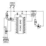
I'd like to ask how is it with powering these rf modules. I saw recommendations only to power the module when actually transmitting (using a transistor), so that it won't flood the "ether". But when I measure the current flowing through the transmitter, it's practically zero when it's not transmitting (no data being sent to it), so I'm wondering... Do any of the members here have experience with these modules and could enlighten me in this matter?

Thanks in advance!
 

Dippy

Moderator
Hello.
Please provide a link to the exact module and Data Sheet so that people can view the correct device and give you a good answer. Help us to help you.
 

Dippy

Moderator
No current = no transmission. Sounds about right.

The Ebay page says that device is in sleep mode (10uA) when data line grounded. (= no transmission).
Is that what you've done?
In theory this means you can leave it powered and simply activate it by sending data to it.
Have you tried any TTL signal into data line and measuring current?
Power it off same V+ as PICAXE (e.g. ~5V) to test.

Have you got the receiving module or any receiver capable of accepting 315MHz?
I don't have any experience of this particular module but it looks a typical cheapo Low Q device.
No data sheet so you'll probably find the quality is low as the makers can't provide a spec maybe.
Maybe Q1 triggers the resonator for simple OOK and that's why it 'sleeps' with no data.

Show us a schematic (circuit diagram) of exactly how you are testing it.
 

geoff07

Senior Member
It looks like a simple SAW oscillator. Most likely, an input signal (=1=high) makes it oscillate and no input (=ground=low) stops it.

You are right that no power in=no power out. Transmitters are generally rated according to input power because input power is generally dc whilst hf output power is very hard to measure, being affected by all kinds of things including swr, antenna losses etc.

It is the kind of transmitter you get in car remote locking devices, power socket remote switches, etc.

As Dippy suggests, tell us more and you will get more help.
 

0rphu

New Member
Thanks a lot guys, you are right. I started asking from somewhere in the middle of the question in hope of a fast answer - that's a wrong approach, sorry about that.

So here's what I'm currently working on:
It should be a remote temperature sensor. Gets the temperature from DS18B20, sends it with rfout to the rf module (I'm using the 433Mhz version, because that's the allowed frequency here. Then it sleeps for about 5 minutes, and starts over.
temp_sensor.jpg
The schematic looks really ugly, guess I didn't learn to draw a nice one yet. The pins of the rf module: 1 is data, 2 is Vcc, 3 is GND.

I have it built on a breadboard and it's working OK.

The receiver part is a matching 433Mhz receiver (bought with the above mentioned transmitter as a set), an NKM2401, connected to Raspberry Pi.

So is the transmitter part more or less OK? Can I leave it like that?

Thanks again
 

geoff07

Senior Member
If I read it right, the led is connected to ground at both ends. Also the tx ground isn't connected to -ve.

Howwever, then test is does it work. You say it does so there isn't much more to worry about, apart from transfering it from the breadboard to a pcb or stripboard. For that the circuit needs to be correct and clear or errors will creep in.
 

0rphu

New Member
Well, that LED there is actually used as a lead from the rf module to the ground. If we're transmitting, there's current, LED lights up. Don't know whether this is a valid approach, but it works. I'm only wondering abut the value of R4 which could be limiting the current for the rf module. Maybe it could be left out? But could it then draw too much current through the rf module and possibly damage it?

Nah, on the second thought, that GND pin of the rf module is supposed to be connected directly to the ground, so it won't matter whether I put there an LED. LED will only get as much current as the rf draws itself... Or at least that's what I think. So I'm probably just lowering the tx power by putting that resistor there...
 

Dippy

Moderator
Ummm... you're new to this aren't you :)

NEVER put anything like that LED between the module GND and your zero volts ground.
RF modules need a good ground and an LED+res will drop volts. Remove it.


And don't put it in the supply line either. LEDs DROP volts.
 

0rphu

New Member
Told you I was new to this... LED and res removed. And the range improved somehow :). Another valuable lesson learned today, thanks! This is not actually a thing fit for trial and error approach. Sometimes it works even when there's an error. It just doesn't work that well.
 

srnet

Senior Member
Also, with the LED in circuit the GND pin of the RF module (3 ?) the ground pin is at circa 2V above ground.

So when you are applying a logic 0 to the control pin (PICAXE pin 18) your pulling the radio module control pin below the radio modules ground. This may result in damage to the radio module.
 

0rphu

New Member
I had that feeling that LED isn't just a piece of wire that emits light as a bonus :). No seriously, I didn't think that through. Thanks for all the insight.
 
Top