ebay clock module "I2C RTC DS1307 AT24C32 Real Time Clock Module"

ChrisSeymour

New Member
I'm a Newbie re the forum, electronics and picaxe so please forgive me and let me know if I'm breaking any rules 'n stuff :)

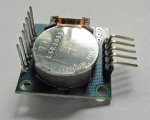
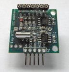
I purchased the above module from ebay. It appears to be a really useful module with rtc and eeprom.

My first attempt at making it work was rather disappointing and continues.

Thanks to the rapid and helpful responses already from everyone who replied to my original posting.

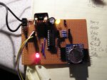
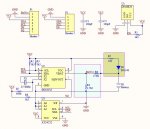
I'm using a 14 pin picaxe (14M2) with B.3 (scl) and B.4 (sda) and a 4.5v battery pack.

I connected the GND, VCC, SCL and SDA but all I can read into the picaxe chip is FF for each byte. I didn't use SQ or DS (2 labels shown on the module pcb). For pullups I used 4k7 resistors. I guess that I'm missing something rather than there being an issue with the ebay purchase. For info I've copied my code below:

Code:
hi2csetup i2cmaster, %11010000, i2cslow, i2cbyte		; set PICAXE as master and DS1307 slave address

; write time and date e.g. to 11:59:00 on Thurs 25/12/03
symbol seconds = b0
symbol mins = b1
symbol hour = b2
symbol day = b3
symbol date = b4
symbol month = b5
symbol year = b6
symbol control = b7

start_clock:
'	let seconds = $00						; 00 Note all BCD format
'		let mins = $59							; 59 Note all BCD format
'		let hour = $11							; 11 Note all BCD format
'		let day = $03							; 03 Note all BCD format
'		let date = $25							; 25 Note all BCD format
'		let month = $12							; 12 Note all BCD format
'		let year = $03							; 03 Note all BCD format
'		let control = %00010000						; Enable output at 1Hz
'		hi2cout 0,(seconds,mins,hour,day,date,month,year,control)

hi2cin 0,(b0,b1,b2,b3,b4,b5,b6,b7)			; read time and date and debug display	
	debug b1
	pause 2000
	goto start_clock
Thanks for the pointer to the wizards to set the clock. The wizard program appeared to download to set the time and run ok. I therefore commented out the clock setting stuff from my code above but still no joy.

Cheers, Chris
 
Last edited:

ChrisSeymour

New Member
You haven't answered this question:
Sorry I've got the laptop on my knees and the breadboard on the arm of the chair and so a little distracted. It does have a battery fitted to the module.

I had a look at the code generated by the wizard and added debug 'n stuff. It "appears" to be failing to communicate with the rtc. The wizard generated code writes to the rtc and then reads it again to check its set. The check fails.

I replaced the batteries in the battery pack to ensure I got as close to 4.5v (the original battery set were running low).

The rtc now returns $D1, $FF, $FF, $FF, $FF, $FF, $FF, $FF. i.e. $D1 in seconds rather than the original $FF. I don't know whether the change is battery related so will test again with the old batteries.

I am a little suspicious of the DS pin on the module but can't see what its supposed to be for. The ebay item shows the DS pin should be connected to the arduino but I have no idea what its needed for or what the picaxe should feed it.

I tried removing the module from the breadboard and I got all $FF which is what I'd expect. Replacing the module once more gives the $D1 so there is a small difference with the module in place but not a lot!

Cheers, Chris
 

westaust55

Moderator
To recapitulate on the post which I made in the other thread whrer Christ had first posted (where nick12ab extracted the question from):
========================================
@Chris,

welcome to the PICAXE forum.

I'm using a 14 pin picaxe with B.3 (scl) and B.4 (sda).
Please confirm that the chips is a 14M2 and not the earlier 14M. That the PE is not giving a syntax error sugegsts it is a 14M2 with i2c but good to clarify.

I didn't use SQ or DS
What do you mean by "DS"?

Does the RTC board have a back-up battery fitted?
If not, then you need to pull the Vbat pin down to 0V before the DS1307 will function.

What voltage are you operating the PICAXE and the DS1307 RTC at?
The minimum supply voltage for the RTC is 4.5 Volts - really needs a nominal 5 Volt supply.

On first application of power to the DS1307, the time and date registers are typically reset to 01/01/00 01 00:00:00 (MM/DD/YY DOW HH:MM:SS).
Thus if you are reading back $FF this suggests the pull up resistors are working but there is no comms with the DS1307.
You might want to recheck the wiring to your RTC chip.
===================================================

Okay from later information seems the clock module has a battery on the underside. Is that battery good - as in has 3 Volt across its terminals.
 

ChrisSeymour

New Member
westaust55,

The module battery has power (LIR2032 3.6v shown) even though my meter shows over 4v! Also swapped out with a new CR2032 for testing but no change.

My power supply is from 3 new AA batteries so 4.5V

DS is a pin on the module but I don't know what its for.

By the sound of things I've either got a duff module, I need to boost the voltage or there's something I need to do with DS.

I'll let you know how I get on.

Thanks for the help.

Cheers, Chris
 
Last edited:

Jeremy Harris

Senior Member
My experience with the ordinary DS1307 is that it stops working at around 4.5 V (the datasheet minimum). It may well be that the voltage from 3 AA cells is marginal, based on my own experience.

The SQ pad will be the square wave 1 Hz output from the DS1307, I believe, and the DS pad will probably be associated withe the on-board 32k EEPROM, maybe an address select line.
 

nick12ab

Senior Member
The module battery has power (LIR2032 3.6v shown) even though my meter shows over 4v! Also swapped out with a new CR2032 for testing but no change.
The problem is that the DS1307 disables access via the i2c bus when the normal power supply is below a certain level. As it has a 3.6V (rechargeable?) battery then this doesn't allow the power supply to be much below 5V. Substituting that with a 3V non-rechargeable might be unsafe.
 

SAborn

Senior Member
The backup battery of 3.6v (even 4v) is fine and is normal, so i would not stress about that, and will last over 10 years in backup mode so hardly a high power requirement device in standby.
 

JimPerry

Senior Member
I've got this module and it works a treat - check the wiring ...

DS is Device Select methinks for the EEPROM.

EDIT:My unit has 3K3 pullup resistors prefitted - so yours may screw it up.
 

Attachments

Last edited:

ChrisSeymour

New Member
I've got this module and it works a treat - check the wiring ...

DS is Device Select methinks for the EEPROM.

EDIT:My unit has 3K3 pullup resistors prefitted - so yours may screw it up.
I tried 4k7 pullup resistors initially since this what I saw documented for the I2c bus. After that didn't work I tried increasingly higher resistors to ensure the pullups didn't interfere with a weak output from the module. Once I got high enough to discount that theory I decided to go lower until I got to zero and that didn't work either. The fact that your module is working and haven't identified anything I've done differently to me suggests that I could have a duff module. For a couple of quid I've ordered another one from the same supplier and if I find a difference in the new one then I'll send the faulty one back, provided it doesn't cost more in postage! If there isn't a difference and the new one doesn't work then I'll check my circuit for the 100th time :)

I think the spec of the module is really powerful so provided I can get one in 2 working for a couple of quid each I can accept a 50% failure. It is possible (tho unlikely due to the distance of the headers from the chips) that I fried it when soldering in the header pins. For now I'll wait for the new module to arrive. All I have to do is wait a month for delivery!

I may be gone sometime........

Please accept my thanks to all who have tried to help. Its very much appreciated. :)

Just a thought... The module that's working, jpeg evidence given.... it has an undisclosed power supply that I believe is being reduced with a diode by 0.7V. Can you tell me what voltage is being supplied to the module? I'm guessing 5.3V.... as I say its just a guess but it could be significant.

Cheers, Chris
 
Last edited:

g6ejd

Senior Member
ChrisSeymour said "The ebay item shows the DS pin should be connected to the arduino but I have no idea what its needed for or what the picaxe should feed it."

DS is the data line of an DS18B20 temperature device that can be fitted to these boards. You should leave it open-cirucit unless of course you fit a 18B20 and want to read the temperature!

The EEPROM is at address 0
 

ChrisSeymour

New Member
That's really useful. I intend to build a monitoring solution for my conservatory using this module and a picaxe to provide temperature monitoring throughout the day, automated roof blinds, bluetooth connectivity to my home automation and all powered via small solar panels in the roof.

Once again thanks everyone for your help.

Cheers, Chris
 

russbow

Senior Member
I have two of these modules in use. They are excellent.

I am away from home at the mo, so can't access my code.

Use standard code and access as per normal RTC. The I2C address is the same.

Look carefully at your board, you will see an un-populated 3 pin transistor outline.

This is for a temperature sensor, the Rev-Ed DSB thingy. The DS pin is the output for this. It is not a device select pin.

When I get home, I will post the data sheet if still needed.
 

ChrisSeymour

New Member
BTW. If I do get it to work then all contributions will be gratefully included in any documentation or presentation of the solution.

Cheers, Chris
 

ChrisSeymour

New Member
JimPerry,

I too tried an 18M2 (+) earlier but couldn't make it work so since I was testing a number of things at the same time switched the 18 pin to an lcd project and used a 14m2 for this rtc project instead. Its all adding fuel to the idea that this particular module is duff. I'll be back here in 30 days to let you know how I get on with the second module.....

Thanks.

All (positive) contributions gratefully accepted :)

Cheers, Chris
 

westaust55

Moderator
The backup battery of 3.6v (even 4v) is fine and is normal, so i would not stress about that, and will last over 10 years in backup mode so hardly a high power requirement device in standby.
Sorry SAborn, but the 4V not correct for the DS1307. From the datasheet:

The nominal power-fail trip point (VPF) voltage at which access to the RTC and user RAM is denied is set by the internal circuitry as 1.25 x VBAT nominal.
If the backup battery was 4 Volts then the power fail point would be 4 * 1.25 = 5 Volts and the DS1307 would thus at 5 Volts or lower switch to battery backup.
At 3.6 Volts on the back-up battery the trip point would be 4.5V so unless the main battery was new to get better than 4.5 Volts again the DS1307 detects as a power fail point switch to battery backup and there is no access to the registers or RAM.


EDIT:
also from the datasheet:

Battery voltage must be held between the minimum and maximum limits for proper operation. Diodes in series between the battery and the VBAT pin may prevent proper operation.
and
VBAT Battery Voltage: minimum = 2.0 V typical = 3 V and maximum = 3.5 V
 
Last edited:

SAborn

Senior Member
Sorry SAborn, but the 4V not correct for the DS1307. From the datasheet:
Thanks for the correction Westy.
I actually knew that, but its been a while since i made circuits for the RTC and been using exsisting boards, so had forgotten.

I blame that on being a "Senior Member" as i now have "Senior Moments" ;)
 

russbow

Senior Member
@Chris. I wanted to store data to the integral EEPROM on this board, but struggled with some of the conditional statement. IE. if hours are 23 and minutes are 59, then store it.

This thread helped

http://www.picaxeforum.co.uk/showthread.php?20085-Conditional-commands&highlight=russbow

You will find the complete code that I used on there. I did not put a temperature sensor on the board, so the DS pin can be ignored.

Working on an 08m2, but easily ported to any other Picaxe.

R.
 

eclectic

Moderator
@Chris
Just out of interest, I bought one of these modules
from a Brit supplier.
(More expensive, but only two days delivery).

Two sets of connectors;
1. Con042 right angle.
http://www.techsupplies.co.uk/epages/Store.sf/en_GB/?ObjectPath=/Shops/Store.TechSupplies/Products/CON042
2. Long pin socket connectors.
http://www.rapidonline.com/Cables-Connectors/Wirewrap-turned-pin-2-54mm-SIL-sockets-63762

AXE091 board. 18M2 at 5.0 volts

1k resistor in line with an LED

Programmed by the Time setting Wizard.

Then read back the time and data each second.

Flashing LED and readout worked perfectly first time.

Just confirming what the others have said.

e
 

Attachments

JimPerry

Senior Member
My board is slightly different silkscreened pin names on both sides and no through holes bottom right (your first pic).
 
ChrisSeymour said "The ebay item shows the DS pin should be connected to the arduino but I have no idea what its needed for or what the picaxe should feed it."

DS is the data line of an DS18B20 temperature device that can be fitted to these boards. You should leave it open-cirucit unless of course you fit a 18B20 and want to read the temperature!

The EEPROM is at address 0
My board is slightly different than what is shown on the schematic. (No resistor between battery and RTC, etc.)
But connecting it up by following this schematic still worked quite nicely. I bought two of them. One keeps time very well, the other gains about three minutes a day.

EEPROM&RTCebay.jpg
 

hippy

Ex-Staff (retired)
My board is slightly different than what is shown on the schematic. (No resistor between battery and RTC, etc.)
Seems interesting that battery circuit - I'm wondering if it's for use with a SuperCap or small rechargeable rather than a Lithium battery ?
 

ChrisSeymour

New Member
Thanks to everyone who has contributed to this thread. After investing in a 5V power supply to test the module and still no joy I've concluded that the board I have is duff. I ordered another one before I went on holiday so hopefully it should arrive in a couple of weeks.

I'll post my results. Hopefully they'll be positive next time! :)

Cheers, Chris
 

eclectic

Moderator
Thanks to everyone who has contributed to this thread. After investing in a 5V power supply to test the module and still no joy I've concluded that the board I have is duff. I ordered another one before I went on holiday so hopefully it should arrive in a couple of weeks.

I'll post my results. Hopefully they'll be positive next time! :)

Cheers, Chris
Why wait that long?

See post #26. :)

e
 

MartinM57

Moderator
I bought two of them. One keeps time very well, the other gains about three minutes a day.
Interesting - 3 minutes per day is basically saying that it's duff.

Bearing in mind other threads about the provenance of components bought on the well known auction site at cheaper than believable prices (you can't buy a DS1307, a dataflash chip, a crystal, a few SMD components, a PCB, a coin cell battery holder and a rechargeable coin cell in the UK for anything like £1.98) , any thoughts on these?
 

russbow

Senior Member
Any ideas on the purpose of R4, 5 and 6 and D1 as shown on the diagram in post #30.
My homebrew board has the battery connected directly to the chip pin. Works OK.

I have 2 of these modules. Time keeping is perfectly OK, but a reload is needed after 3 days power down.
Fake batteries ??
 
Top